
Specifications

7SR242 Duobias Description Of Operation
Section 2: Hardware Description
2.1 General
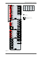
The structure of the relay is based upon the Multi-function hardware platform. The relays are supplied in either
size E8 or size E10 cases (where 1 x E = width of approx. 26mm). The hardware design provides commonality
between products and components across the Multi-function range of relays.
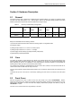
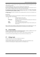
Table 2-1 Summary of 7SR24 Relay Configurations
Relay Current
Inputs
Voltage
Inputs
Binary
Inputs
Output
Relays
LEDs Case
7SR2422 8 1 9 6 16 E8
7SR2423 8 1 19 14 24 E10
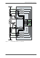
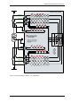
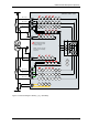
Relays are assembled from the following modules:
1) Front Fascia with three fixed function LEDs and ordering options of configurable LEDs.
2) Processor module
3) Analogue Input module ‘A’: 3 x Current + 6 x Binary Inputs
4) Analogue Input module ‘B’: 5 x Current + 1 x Voltage.
4) Power Supply and basic Binary Input (BI) and Binary Output (BO).
5) Optional Binary Input/Output Module
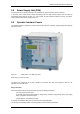
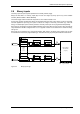
2.2 Case
The relays are housed in cases designed to fit directly into standard panel racks. The two case options have
widths of 208mm (E8) and 260 mm (E10), both have a height of 177 mm (4U). The required panel depth (with
wiring clearance) is 242 mm. An additional 75 mm depth clearance should be allowed to accommodate the
bending radius of fibre optic data communications cables if fitted.
The complete relay assembly is withdrawable from the front of the case. Contacts in the case ensure that the CT
circuits remain short-circuited when the relay is removed.
The rear terminal blocks comprise M4 female terminals for wire connections. Each terminal can accept two 4mm
crimps.
Located at the top rear of the case is a screw clamp earthing point, this must be connected to the main panel
earth.
2.3 Front Cover
With the transparent front cover in place the user only has access to the and TEST/RESET buttons,
allowing all areas of the menu system to be viewed, but preventing setting changes and control actions. The only
‘action’ that is permitted is to reset the Fault Data display, latched binary outputs and LEDs by using the
TEST/RESET button.
The front cover is used to secure the relay assembly in the case.
©2010 Siemens Protection Devices Limited Chapter 1 Page 13 of 52