
Specifications

7SR242 Duobias Description Of Operation
2.8 Binary inputs
The binary inputs are opto-couplers operated from a suitably rated dc supply.
Relays are fitted with 9 or 19 binary inputs (BI). The user can assign any binary input to any of the available
functions (INPUT CONFIG > INPUT MATRIX).
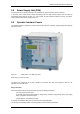
The Power Supply module includes the relay basic I/O. The module includes 3 x BI.
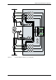
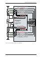
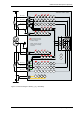
Pick-up (PU) and drop-off (DO) time delays are associated with each binary input. Where no pick-up time delay
has been applied the input may pick up due to induced ac voltage on the wiring connections (e.g. cross site
wiring). The default pick-up time of 20ms provides ac immunity. Each input can be programmed independently.
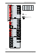
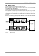
Each input may be logically inverted to facilitate integration of the relay within the user scheme. When inverted the
relay indicates that the BI is energised when no d.c. is applied. Inversion occurs before the PU & DO time delay,
see fig. 2.8-1.
Each input may be mapped to any front Fascia indication LED and/or to any Binary output contact and can also
be used with the internal user programmable logic. This allows the relay to provide panel indications and alarms.
Event
BI 1
Binary Input 1
=1
Inverted Inputs
BI 1 inverted
BI 1 P/U Delay
Event
BI n
Binary Input n
=1
BI n inverted
BI n P/U Delay
INPUT CONFIG>
INPUT MATRIX
(Or gates)
Logic signals,
e.g. '51-1 Inhibit'
BI 1 D/O Delay
BI n D/O Delay
INPUT
CONFIG>
BINARY
INPUT
CONFIG
Figure 2-2 Binary Input Logic
©2010 Siemens Protection Devices Limited Chapter 1 Page 17 of 52