
Specifications


7SR242 Duobias Applications Guide
©2010 Siemens Protection Devices Limited Chapter 7 Page 4 of 56
List of Figures
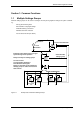
Figure 1-1 Example Use of Alternative Settings Groups ......................................................................5
Figure 1-2 Example of Transformer Alarm and Trip Wiring .....................................................................6
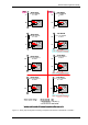
Figure 1-3 – Binary Input Configurations Providing Compliance with EATS 48-4 Classes
ESI 1 and ESI 2 ...................................................................................................................8
Figure 2-1 Procedure for calculating Overall Differential Protection Settings........................................10
Figure 2-2: 87BD Characteristic.............................................................................................................13
Figure 2-3: Differential Highset Characteristic .......................................................................................15
Figure 2-4 New Transformer Application ...............................................................................................16
Figure 2-5: AC Connections - Example 1...............................................................................................16
Figure 2-6 ICT Settings – Example 1 .....................................................................................................17
Figure 2-7: Relay Currents - Star Winding Internal Earth ......................................................................19
Figure 2-8: Relay Currents - Star Winding Internal Phase Fault............................................................20
Figure 2-9: Relay Currents - Delta Winding Internal Earth Fault ...........................................................21
Figure 2-10: Relay Currents - Delta Winding Internal Phase Fault........................................................21
Figure 2-11 Relay Replacement.............................................................................................................23
Figure 2-12: AC Connections - Example 2.............................................................................................23
Figure 2-13 Summary of ICT Settings....................................................................................................24
Figure 2-14 IEC NI Curve with Time Multiplier and Follower DTL Applied ............................................27
Figure 2-15 IEC NI Curve with Minimum Operate Time Setting Applied ..............................................27
Figure 2-16 Overcurrent Reset Characteristics......................................................................................28
Figure 2-17: REF Protection Applied to a Delta/Star Transformer.........................................................29
Figure 2-18: AC Connections: REF........................................................................................................29
Figure 2-19 Thermal Overload Settings.................................................................................................33
Figure 2-20 NVD Application..................................................................................................................35
Figure 2-21 NVD Protection Connections ..............................................................................................35
Figure 2-22 Load Shedding Scheme Using Under-Frequency Elements..............................................37
Figure 3-1 CT Requirements..................................................................................................................40
Figure 4-1 Example Use of Quick Logic.................................................................................................41
Figure 5-1 - Circuit Breaker Fail .............................................................................................................44
Figure 5-2 - Single Stage Circuit Breaker Fail Timing............................................................................44
Figure 5-3 - Two Stage Circuit Breaker Fail Timing...............................................................................45
Figure 5-4: Trip Circuit Supervision Scheme 1 (H5) ............................................................................46
Figure 5-5: Trip Circuit Supervision Scheme 2 (H6) ............................................................................47
Figure 5-6: Trip Circuit Supervision Scheme 3 (H7) ............................................................................47
Figure 5-7 Close Circuit Supervision Scheme .......................................................................................48
Figure 6-1: Relay Currents – External Earth Fault with In Zone Earthing Transformer.........................49
Figure 6-2: Relay Currents – External Earth Fault with In Zone Earthing Transformer.........................50
Figure 6-3 7SR24 Applied to Yd Transformer with an In Zone Earthing Transformer...........................50
Figure 6-4: 51
Figure 6-5 – AC Connections: Yd9, 90
0
Transformer – Non-standard Secondary
Connections.......................................................................................................................52
Figure 6-6 AC Connections: Yd9, 90
0
Transformer – Standard Secondary Connections .....................53
Figure 6-7 Dyn11 Transformer with Reverse Phase Notation ...............................................................54
Figure 6-8: AC Connections for Auto-Transformer Overall Protection...................................................55
Figure 6-9: AC Connections for Auto-Transformer Overall and REF Protection ...................................55
Figure 6-10 AC Connections for Reactor and Connections Protection..................................................56
List of Tables
Table 2-1 The Effect of ICT Selection on Protection Settings................................................................22