
Specifications


7SR242 Duobias Applications Guide
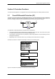
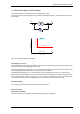
When a through fault occurs, saturation of one or more CTs may cause a transient differential current to be
detected by the relay. The bias slope limit is chosen to ensure the biased differential function is stable for high
through fault currents coincident with CT saturation. This setting defines the upper limit of the bias slope and is
expressed in multiples of nominal rated current i.e. the lower the setting the more stable the protection.
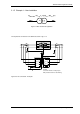
The three phase through fault current can be estimated from the transformer impedance. For a typical grid
transformer of 15% impedance, the maximum through fault will be 1/0.15 = 6.66 x rating. A setting value is
chosen that introduces the extra bias at half of the three phase through fault current level of the transformer, so
6.66/2 = 3.33 and a setting of 3 would be selected as the nearest lower setting available.
87BD 2
nd
Bias Slope Type (Line, Curve)
87BD 2
nd
Bias Slope Setting (1.0 to 2.0 – applied to ‘Line’ only)
These settings are chosen to ensure the biased differential function is stable for high through fault currents
coincident with CT saturation.
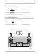
87BD Inrush Action
Harmonic bias is used to prevent relay operation during magnetising inrush current into one winding when the
transformer is first energised.
The recommended setting is ENABLED - see section 5.1.
87BD Overfluxing Action
This setting can be used to prevent operation of the 87BD elements in the presence of allowable over-fluxing
conditions - see section 5.2.
87BD Time Delay Setting
A 5ms setting is recommended where the circuit is cabled to ensure stability during resonant conditions.
©2010 Siemens Protection Devices Limited Chapter 7 Page 14 of 56