
Specifications


7SR242 Duobias Applications Guide
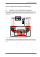
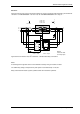
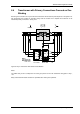
6.3 Transformer with Primary Connections Crossed on Both
Windings
Yd11 Transformer Connected as Yd9 (90
0
)
The phase-shift between the W1 and W2 primary systems may necessitate that primary connections to each
winding of the transformer have to be crossed. Fig. 6.4-1 shows a typical arrangement where a Yd11 transformer
is arranged to give a primary system phase-shift of 90q by crossing of its main connections. There are two
optional methods of configuring the 7SR24 relay.
Solution 1
Fig. 6.4-1 shows W1 and W2 CT secondary wiring crossed over to replicating the crossovers on the transformer
primary connections:
W1/W2
Yd11 (30
o
)
1718
12
56
910
1413
I
G1
21
65
109
W1 I
L1
W1 I
L2
W1 I
L3
ICT1 = Yd11 ICT2 = Ydy0
A
1718
I
G2
12
56
910
W2 I
L1
W2 I
L2
W2 I
L3
A
B
NOTES
CTs shown wired
to 1A relay inputs
a
c
b
CB
A
A
B
C
a
b
c
A-N = b-c
B-N = c-a
C-N = a-b
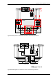
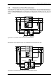
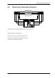
Figure 6-5 – AC Connections: Yd9, 90
0
Transformer – Non-standard Secondary Connections
Notes:
An advantage of the above is that the 7SR24 relay can be set to correspond to the vector group shown on the
main transformer rating plate i.e. Yd11, +30° simplifying installation. This approach is also applicable where the
transformer is used to reverse the system phase sequence – see section 6.5.
A disadvantage is that ‘non-standard’ secondary wiring connections are used.
Relay instruments will indicate ’transformer’ quantities rather than system quantities.
©2010 Siemens Protection Devices Limited Chapter 7 Page 52 of 56