
Installation Instructions

Document No.129-346
Installations Instructions
December 3, 2009
Page 2 of 4 Siemens Industry, Inc.
Installation
Mounting an Actuator to a Valve
CAUTIONS:
• The black actuator attachment
support ring must be in place on
top of the valve bonnet before
installing the actuator.
If the support ring is not in place,
damage to the actuator
connection may result.
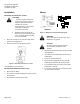
2. SSA61/81: Using the 3mm hex
wrench, rotate the manual override
to the "1" position before installing
on a valve assembly.
1. Place the actuator on the valve and firmly hand-
tighten the coupling piece.
2. Connect the wires per the Wiring section.
Figure 2. Mounting an Actuator to a Valve
The installation is now complete.
Removing an Actuator From a Valve
1. Disconnect the wiring.
2. Unscrew the actuator-coupling piece from the valve
body threads.
3. Remove the actuator from the valve.
Wiring
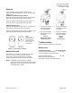
SSA/P61U
SSA81U
Figure 3. SSA/P Series Actuator Wiring Diagram.
WARNING:
Wire connection G is 24 Vac HOT on the
SSA/P61U, not ground.
CAUTION
:
G0 and G must be properly wired for
correct function and full life of the
actuator.
• All wiring must conform to NEC and local codes
and regulations.
• Use earth ground isolating step-down Class 2
transformers.
• Do not use autotransformers.
• Determine the supply transformer rating by
summing the total VA of all actuators used.
• The maximum rating for a Class 2 step-down
transformer is 100 VA.
• It is recommended that one transformer power
no more than 10 actuators.