
Installation Instructions

Document No. 129-346
Installation Instructions
December 3, 2009
Siemens Industry, Inc. Page 3 of 4
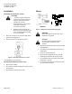
Start-up
Check the wiring and the position indication. See
Figure 4 for referred positions "0" and "1" on the position
indicator disc.
SSA61U and SSA81U Normally Closed
When the position indicator disc is at the "0" position the
output shaft is extended (two-way valve closed).
When the position indicator disc rotates to position "1",
the output shaft is retracted (two-way valve open).
SSP61U Normally Open
When the position indicator disc is at the "0" position the
output shaft is retracted (two-way Valve open).
When the position indicator disc rotates to position "1" the
output shaft is extended (two-way valve closed).
Position 0
Position 1
Figure 4. Visual Position Indication.
Manual Override
The actuators can be driven manually to any position
between "0" and "1" with a 3 mm hex wrench.
See Figure 5. A control signal from the controller,
however, will take priority over any manual position.
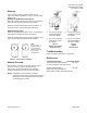
NOTE: The SSA61U and the SSP61U calibrate
(calibration stroke) during commissioning. Correct
functioning cannot be guaranteed if the actuator
is operated without a valve.
• (A) Turn hex wrench
counterclockwise to
retract the spindle.
• (B) Turn hex wrench
clockwise to extend
the spindle.
• A) Turn hex wrench
clockwise to extend
the spindle.
• (B) Turn hex wrench
counterclockwise to
retract the spindle.
Figure 5.
SSA61U and SSA81U
Normally Closed.
Figure 6.
SSP61U
Normally Open.
Troubleshooting
Check the wiring for the proper connections.
References
Technical Instructions Document Number
SSA/P Electronic Valve Actuator 155-710
24 Vac 3-Position or 0-10 Vdc Control
Technical Bulletin TB254 155-291
599 Series Zone Valves Electric
and Thermic Actuator Assembly Selection
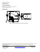
Note:
The "0" and "1"
position markings
are intended for
reference only and
not for stroke
measurement
.