
Data Sheet for Product


Powermite 599 MT Series Terminal Unit 2-way Valves Technical Instructions
Document Number 155-196P25
June 17, 2020
Siemens Industry, Inc. Page 9
Sizing, continued
The following variables must be determined:
• The medium to be controlled: water, etc.
• The maximum inlet temperature and pressure of the medium at the valve.
• The pressure differential that will exist across the valve under maximum load
demand.
• The maximum capacity the valve must deliver.
• The maximum line pressure differential the valve actuator must close against.
See Application Bulletin (AB)-1 Control Valve Selection and Sizing (155-285) for further
recommendations.
Mounting and
Installation
Install the valve so that the flow follows the direction of the arrow indicated on the valve
body.
For best performance, install the valve assembly with the actuator above the valve body.
The valve and actuator can be installed in any position between vertical and horizontal. It is
not recommended to install the valve assembly so that the actuator is below horizontal or
upside-down.
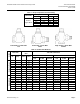
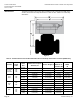
Allow sufficient space for servicing the valve and actuator. See Table 11 for valve body
dimensions. See Figure 4 and Table 10 for dimensions of the service envelope
recommended around the actuator.
NOTE: Instructions for field mounting an actuator, wiring diagrams, and start-up are
covered in the Technical Instructions and Installation Instructions for each
actuator.
Service
Replace the valve if inoperable.
Disposal
Do not dispose of the valve as household waste.
• Special handling of individual components may be mandated by law or make
ecological sense.
• Observe all local and currently applicable laws and regulations.
The actuators are considered electrical and electronic equipment for
disposal in terms of the applicable European Directive and may not be
disposed of as domestic garbage.
• Dispose of the actuators through channels provided for this
purpose.
• Comply with all local and currently applicable laws and regulations.