
Data Sheet for Product

Technical Instructions MT Series SSC Electronic Valve Actuator, 24 Vac Floating Control
Document Number 155-314P25
May 8, 2019
Page 4 Siemens Industry, Inc.
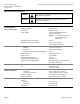
Calibration Stroke
The SSC81.5U writes its calibration stroke parameters to nonvolatile memory on the
first startup of the actuator. Successive startups bypass the calibration stroke unless the
memory is manually cleared. If installing the actuator on a different valve (such as on a
replacement valve), manually clear the calibration stroke from memory as follows:
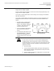
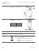
1. Remove the terminal cover using a Phillips
head screwdriver.
2. Locate hole on the circuit board shorting
bars.
3. Insert and gently twist a flat-blade
screwdriver to electrically connect the
shorting bars (Figure 2). The SSC81…
then performs a new calibration stroke.
4. Secure the terminal cover back in place.
Figure 2. Manually Clearing Calibration
Stroke from Memory.
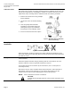
Mounting and
Installation
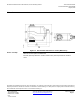
Mount the actuator in one of the allowable positions shown in Figure 3.
Figure 3. Mounting Position.
When mounting the actuator in a plenum, the proper cable must be attached to meet
local codes. Allow 8 inches (200 mm) above the actuator and 8 inches (200 mm) behind
the cable for service.
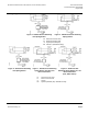
Wiring
Use earth ground isolating, step-down Class 2 transformers. Do not use
autotransformers.
Determine supply transformer rating by summing total VA of all actuators used. The
maximum rating for a Class 2 step-down transformer is 100 VA.
Do not power more than 10 actuators by one transformer. (Use a 0.5-amp fuse on
secondary actuator.)
Because the triacs on TECs and DXRs always switch hot power, add a 1000 Ohm 2-
Watt resistor across each of the binary (Y1, Y2) outputs (see Figure 8). The two
resistors must be used for all hot-switching triacs not just TEC and DXR.
NOTE: Can be wired either neutral or hot switched.
CAUTION:
Terminals must be properly wired for correct function and full life of the
actuator.