
Data Sheet for Product
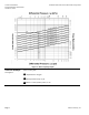
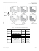
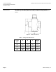
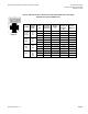
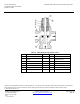
Table Of Contents
- Table 2. Body Temperature-Pressure Rating.
- Table 3. Maximum Water Capacity - U.S. Gallons per Minute.
- Table 4. Maximum Water Capacity - Cubic Meters per Hour (m3/hr).
- Figure 1. Water Capacity Graph.
- Table 5. Close-off Pressures for Electronic Actuators.
- Table 6. Maximum Available Close-off Pressures for Pneumatic Actuators.
- Table 7. 3-Way Valve Dimensions.
- Figure 5.

Powermite 599 Series MT Terminal Unit 3-way Valves Technical Instructions
Document Number 155-197P25
October 27, 2015
Siemens Industry, Inc. Page 7
Sizing
The sizing of a valve is important for correct system operation. An undersized valve will
not have sufficient capacity at maximum load. An oversized
valve can initiate cycling, and
the seat and throttling plug can be damaged because of the restricted opening. Correct
sizing of the control valve for actual expected conditions is considered essential for good
control.
The following variables must be determined:
The medium to be controlled: water, and so on.
The maximum inlet temperature and pressure of the medium at the valve.
The pressure differential that will exist across the valve under maximum load demand.
The maximum capacity the valve must deliver.
The maximum line pressure differential the valve actuator must close against.
See Application Bulletin (AB)-1 Control Valve Selection and Sizing (155-285) for further
recommendations.
See Tables 3 and 4 for valve capacities.
Mounting and
Installation
Install the valve so that the flow follows the direction of the arrow indicated on the valve
body.
For best performance, install the valve assembly with the actuator above the valve body.
The valve and actuator can be installed in any position between vertical and horizontal.
It is not recommended to install the valve assembly so that the actuator is below
horizontal or upside down.
Allow sufficient space for servicing the valve and actuator. See Table 7 for valve body
dimensions. See Figure 5 and Table 8 for dimensions of the service envelope
recommended around the actuator.
NOTE: Instructions for field mounting an actuator, wiring diagrams, and start-up
are covered in the Technical Instructions and Installation Instructions for
each actuator.
Service
Replace the valve if inoperable.