
Installation Instructions

Installation Instructions
Document No. 129-253
May 8, 2019
SSC Series Electronic Valve Actuator
Item Number 129-253-07, Rev. FA Page 1 of 5
Product Description
The SSC series actuator requires a 24 Vac, Class 2
supply and provides a 0 to 10 Vdc or Floating (three-
position) control signal. The actuator controls a
Powermite™ 599 Series MT Series valve with a
7/32-inch (5.5-mm) stroke.
Warning /Caution Notations
WARNING:
Personal injury or loss of life
may occur if you do not
perform a procedure as
specified.
CAUTION:
Equipment damage or loss of
data may occur if you do not
follow a procedure as
specified.
Product Numbers
SSC61U 0 to 10 Vdc, proportional control,
non-spring return (fail-in-place)
SSC61.5U 0 to 10 Vdc, proportional control,
spring return (fail-safe)
SSC81U Floating control, non-spring return
(fail-in-place)
SSC81.5U Floating control, spring return
(fail-safe)
Contents
One SSC actuator
Estimated Installation Time
20 minutes
Required Tools
• Small Phillips head screwdriver
• Small flat-blade screwdriver
• Wire stripper
Prerequisites
WARNING:
1. If mounting the actuator to a valve already
in line, either close the shut-off in the
piping (upstream first, then downstream) or
switch off the pump to allow the differential
pressure in the valve to drop.
2. Disconnect the controller power before
replacing the actuator.
3. If high voltage cable is co-located with the
SSC actuator, conduit or shielded wire may
need to be used.
CAUTION:
Before applying power, make certain a valve is
connected to the actuator.
If applying power to the actuator when a valve is
not connected, the actuator will respond to a
control signal and the shaft will extend until it
reaches its maximum end stop. Thereafter, it will
not respond to any signal.
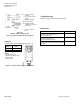
If this occurs, disconnect the power. Turn the
manual position indicator on the top of the
actuator to the 0 position and verify the actuator
shaft retracts completely. See Figure 4.
Connect a valve to the actuator and reapply the
power. The actuator will return to normal
operation.
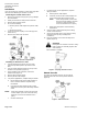
Mounting
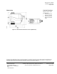
The vertical position is recommended for mounting
the actuator. See Figure 1.
Figure 1.
Acceptable Actuator Mounting Positions.
CAUTION:
Mount actuator at a 45° angle from vertical when
using on low pressure steam systems to reduce
radiant heat that can damage the actuator.