
Installation Instructions

Document No. 129-253
Installation Instructions
May 8, 2019
Siemens Industry, Inc. Page 3 of 5
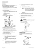
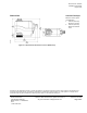
Calibration Stroke
The SSC Series writes its calibration stroke parameters to
nonvolatile memory on the first start-up of the actuator.
Successive start-ups bypass the calibration stroke unless
the memory is manually cleared. If installing the actuator
on a different valve (such as on a replacement valve),
manually clear the calibration stroke from memory as
follows:
1. Remove the terminal cover using a Phillips head
screwdriver.
2. Locate hole on the circuit board with the shorting bars
(Figure 5).
3. With power applied to the unit, insert and gently twist
a flat-blade screwdriver to electrically connect the
shorting bars. The SSC… then performs a new
calibration stroke.
4. Secure the terminal cover back in place.
Figure 5. Manually Clearing Calibration Stroke from
SSC61U and SSC61.5U Nonvolatile Memory.
Wiring
• All wiring must conform to NEC and local codes and
regulations.
• Use earth ground isolating, step-down Class 2
transformers. Do not use autotransformers.
• Determine the supply transformer rating by summing
the total VA of all actuators used. The maximum rating
for a Class 2 step-down transformer is 100 VA.
• Do not power more than 10 actuators with one
transformer. (Use 0.5 amp on secondary actuators.)
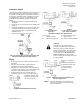
Y2: Retracts actuator shaft
Y1: Extends actuator shaft
G: System potential
Figure 6. SSC81U NSR Floating Control.
Figure 7.
For Non-Triac Driven
Controllers.
Figure 8
For Triac Driven Controllers,
(TEC, DXR, and Others).
SSC81.5U Floating Control SR Hot-Switch.
G, G0: 24 Vac Y1 Extends actuator shaft
operating voltage G System neutral
Y2: Retracts actuator shaft G0 System potential (switched)
CAUTION:
Terminals must be properly wired for
correct function and full life of the actuator.
Because the triacs on TECs and DXRs
always switch hot power, add a 1000 Ohm
2-Watt resistor across each of the binary
(Y1, Y2) outputs (see Error! Reference
source not found.). The two resistors
must be used for all hot-switching triacs not
just TEC and DXR.
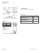
G, G0: 24 Vac operating
voltage
Y2: Retracts actuator shaft
Y1: Extends actuator shaft
G: System potential
G0: System neutral
(switched)
Figure 9. SSC81.5U Floating Control SR Neutral
Switching Applications.
NOTE: For proper operation, it is recommended no
more than three actuators be assigned to any
single control signal.