
Installation Instructions

Document No. 129-253
Installation Instructions
May 8, 2019
Page 4 of 5 Siemens Industry, Inc.
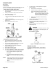
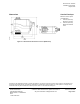
G, G0: 24 Vac operating
voltage
Y: *0 to 10 Vdc control
signal
G: System potential
G0: System neutral
R1: 500 ohm resistor
(optional for 0-20 mA
operation)
Figure 10.
SSC61U, NSR and SSC61.5U, SR,
0 to 10 Vdc Proportional Control Wiring Diagram.
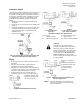
Start-up
Check the wiring and the position indicator (Figure 11).
Position
Indicator
Output
Shaft
0
Retracted
1
Extended
NOTE:
0 and 1 markings are
intended for reference only,
and not stroke
measurement.
Figure 11. Position Indicator (Shown in 0 Position).
Troubleshooting
Check the wiring for the proper connections.
References
Technical Instructions
Document No.
EA 599-15 Powermite 599 Series SSC
Electronic Valve Actuator 24 Vac
Proportional Control
155-313P25
EA 599-16 Powermite 599 Series SSC
Electronic Valve Actuator
3-position (Floating) Control
155-314P25
TB251, Powermite 599 Series, MT Series
Terminal Unit Valve and Actuator Assembly
Selection
155-306P25
*4 to 20 mA with optional
resistor