
Data Sheet for Product

Technical Instructions MT Series SSC Electronic Valve Actuator, 24 Vac/dc Proportional Control
Document Number 155-313P25
January 12, 2018
Page 4 Siemens Industry, Inc.
Operation,
Continued
Calibration Stroke
The SSC61x writes its calibration stroke parameters to nonvolatile memory on the first
start-up of the actuator. Successive start-ups bypass the calibration stroke unless the
memory is manually cleared. If installing the actuator on a different valve (such as on a
replacement valve), manually clear the calibration stroke from memory as follows:
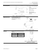
1. Remove the terminal cover using a
Phillips head screwdriver.
2. Locate the hole on the circuit board
with the shorting bars.
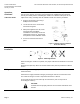
3. With power applied to the unit, insert
and gently twist a flat-blade
screwdriver to electrically connect the
shorting bars (Figure 2). The SSC61x
then performs a new calibration stroke.
4. Secure the terminal cover back in
place.
Figure 2. Manually Clearing Calibration
Stroke from Memory.
Mounting and
Installation
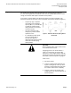
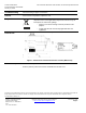
Mount the actuator in one of the allowable positions shown in Figure 3.
Figure 3. Mounting Position.
When mounting the actuator in a plenum, the proper cable must be attached to meet local
codes.
Allow 8 inches (200 mm) above the actuator and 8 inches (200 mm) behind the cable for
service.
Wiring
Use earth ground isolating, step-down Class 2 transformers. Do not use
autotransformers.
Determine the supply transformer rating by summing the total VA of all actuators used.
The maximum rating for a Class 2 step-down transformer is 100 VA.
Do not power more than 10 actuators by one transformer. (Use 0.5 amp fuse on
secondary per actuator.)
CAUTION:
Terminals must be properly wired for correct function and full life of the
actuator.