
Data Sheet for Product

MT Series SSC Electronic Valve Actuator, 24 Vac/dc Proportional Control Technical Instructions
Document Number 155-313P25
January 12, 2018
Siemens Industry, Inc. Page 5
Wiring Diagrams
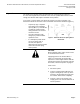
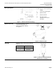
Figure 4. SSC61U and SSC61.5U Wiring.
G, G0 24 Vac or 24 Vdc operating
voltage
Y 0 to 10 Vdc control signal
G0 System neutral
G System potential
R1 500 ohm resistor
(optional for 0 to 20 mA
operation)
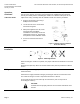
Manual Override
For manual positioning, use the
manual override knob in the
center of the position indicator,
See Figure 5.
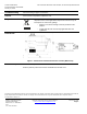
Figure 5. Manual Override.
Start-up
Check the wiring and the position indicator
(Figure 6).
Figure 6. Top View of Position Indicator
(Shown in the 0 Position).
Position Indicator Output Shaft
0 Retracted
1 Extended