Technical Instructions Document No. 155-180P25 September 25, 2018 Flowrite™ 599 Series SKD6xU Electronic Valve Actuators 24 Vac Proportional Control Description Features The Flowrite 599 Series SKD6xU Electronic Valve Actuators require a 24 Vac supply and receive a 0 to 10 Vdc or a 4 to 20 mA control signal to proportionally control a valve. These actuators are designed to work with Flowrite 599 Series valves with a 3/4-inch (20 mm) stroke.
Technical Instructions Document Number 155-180P25 September 25, 2018 SKD6xU Electronic Valve Actuators 24 Vac Proportional Control Specifications Power supply Control signals Operating voltage Frequency Power consumption Control input (Y) 24 Vac -20%/+30% 50/60 Hz 17 VA/12W Voltage 0 to 10 Vdc or 4 to 20 mA (DIP switch selectable) Maximum Impedance 0 to 10 Vdc 100K ohms 4 to 20 mA; 240 ohm Signal resolution <1% Hysteresis 1% Control input (Z) Resistance 0 to 1000 ohms Voltage 0 to 1.
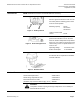
SKD6xU Electronic Valve Actuators 24 Vac Proportional Control Accessories Technical Instructions Document Number 155-180P25 September 25, 2018 NOTE: Installation instructions are included with each accessory. ASC1.6 Auxiliary switch. Sends a signal to indicate the valve is in the 0% stroke position. Switching point is fixed at the 0% stroke position. Switching capacity Figure 1. Auxiliary Switch. Lowest recommended current Figure 2. Stem Heating Element. 24 Vac 4A resistive 2A inductive 10 mA ASZ6.
Technical Instructions Document Number 155-180P25 September 25, 2018 SKD6xU Electronic Valve Actuators 24 Vac Proportional Control Legend SKD Details 1 Pressure cylinder 2 Piston 3 Oscillating pump 4 Return spring 5 Bypass valve 6 Valve stem retainer 7 Manual override knob 8 Position indicator Figure 4. SKD6xU Details. Operation The actuator accepts a 0 to 10 Vdc or a 4 to 20 mA control signal. The actuator mounted on a valve, produces a stroke proportional to the input signal.
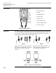
SKD6xU Electronic Valve Actuators 24 Vac Proportional Control Technical Instructions Document Number 155-180P25 September 25, 2018 Mounting and Installation Figure 8. Acceptable Mounting Positions. The vertical position is the recommended position for mounting. Other positions are allowed. When using the Weather Shield for NEMA 3R rating, the vertical position is required. See Weather Shield installation instructions and Figure 8.
Technical Instructions Document Number 155-180P25 September 25, 2018 SKD6xU Electronic Valve Actuators 24 Vac Proportional Control Stroke Calibration, Continued LED Display ON Green Flashing Table 1. LED Status.
SKD6xU Electronic Valve Actuators 24 Vac Proportional Control Technical Instructions Document Number 155-180P25 September 25, 2018 Start-up, Continued 1 2 Figure 11. SKD Electronic Features. DIP Switches (Left to right) 1 Selection of Control Signal 2 Selection of Flow Characteristic ON 4 to 20 mA Modified* OFF Factory Setting 0 to 10 Vdc Default *Changing the default setting will modify an equal percentage valve to a linear flow characteristic.
Technical Instructions Document Number 155-180P25 September 25, 2018 SKD6xU Electronic Valve Actuators 24 Vac Proportional Control Manual Operation Figure 12. The Manual Setting Knob in Manual and Automatic Position. - Turn the manual setting knob clockwise for manual operation. - A red indicator becomes visible as you begin to crank. Each complete revolution (360°) is equal to 3/32-inch (2.5 mm) stroke.
SKD6xU Electronic Valve Actuators 24 Vac Proportional Control Technical Instructions Document Number 155-180P25 September 25, 2018 Wiring Diagrams Figure 13. Connecting Terminals. G G0 Y M U Z 24 Vac System Potential (SP) System Neutral (SN) Control input 0 to 10 Vdc or 4 to 20 mA (DIP switch selectable) Measuring neutral Position indication 0 to 10 Vdc or 4 to 20 mA, (see Table 2. Override control Table 2.
Technical Instructions Document Number 155-180P25 September 25, 2018 SKD6xU Electronic Valve Actuators 24 Vac Proportional Control Dimensions Figure 16. Dimensions of 599-10071 Weather Shield in Inches (Millimeters). Page 10 Siemens Industry, Inc.
SKD6xU Electronic Valve Actuators 24 Vac Proportional Control Technical Instructions Document Number 155-180P25 September 25, 2018 Dimensions, Continued NOTE: The top knockout position should be used when installing the Weather Shield. Figure 17. Dimensions of SKD6xU Actuators in Inches (Millimeters). Information in this publication is based on current specifications. The company reserves the right to make changes in specifications and models as design improvements are introduced.