
Data Sheet for Product

SKD6xU Electronic Valve Actuators 24 Vac Proportional Control Technical Instructions
Document Number 155-180P25
September 25, 2018
Siemens Industry, Inc. Page 9
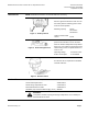
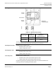
Wiring Diagrams
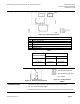
Figure 13. Connecting Terminals.
24 Vac
G
System Potential (SP)
G0
System Neutral (SN)
Y
Control input 0 to 10 Vdc or 4 to 20 mA (DIP switch selectable)
M
Measuring neutral
U
Position indication 0 to 10 Vdc or 4 to 20 mA, (see Table 2.
Z
Override control
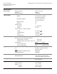
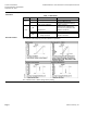
Table 2.
Actuator input signal
Receiving Impedance
Low (<500 Ohm)
High (>10K Ohm)
0 to 10 Vdc
0 to 20 mA
0 to 10 Vdc
4 to 20 mA
4 to 20 mA
2 to 10 Vdc
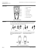
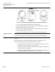
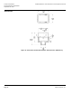
Figure 14. Auxiliary Switch ASC1.6.
System neutral (SN) red
System potential (SP) black
24 Vac/30W
Figure 15. Heating Element
ASZ6.6.
Troubleshooting
• Check that the wires are connected correctly and attached securely.
• Check for adequate power supply.
• Check that the actuator is set for automatic operation. See the Start-Up section.