
Actuator Product Overview

Technical Instructions Flowrite AP 599 Series 4-inch Pneumatic Valve Actuator
Document No. 155-183P25
March 7, 2005
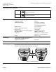
Warning/Caution Notations
WARNING:
Personal injury/loss of life may occur if you do not perform a
procedure as specified.
CAUTION:
Equipment damage may occur if you do not perform a
procedure as specified.
Specifications
Effective diaphragm area 11-inch
2
(71 cm
2
)
Diaphragm material Silicone
Nominal spring range 3 to 8 psi (21 to 55 kPa)
5 to 10 psi (34 to 69 kPa)
10 to 15 psi (69 to 103 kPa)
Nominal stroke 3/4-inch (20 mm)
Maximum diaphragm pressure 35 psi (241 kPa)
Air Connection 1/8-inch NPT
Ambient operating and storage temperature 0 to 225°F (-18 to 107°C)
Mounting location NEMA 1 (interior only)
Dimensions 5-3/4 inch H × 5-1/2 inch diameter
(146 mm H × 137 mm diameter)
Weight 2.5 lb (1.1 kg)
Accessory
Finger Guard Kit (Package of one includes
two half shells, mounting clips, and
installation instructions) 599-10241
Service Kit
Diaphragm replacement kit (Package of one) 599-01093
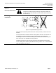
The control air signal upon the diaphragm causes the valve to modulate whenever the
air pressure is within the spring range of the actuator. The actuator spring provides the
necessary force to hold the stem in the stem up position.
Operating
AP0219R1
3/4 in
(20 mm)
Figure 1. Actuator Operation.
Page 2 Siemens Building Technologies, Inc.