
Actuator Product Overview

Flowrite AP 599 Series 4-inch Pneumatic Valve Actuator Technical Instructions
Document No. 155-183P25
March 7, 2005
Complete instructions are included in the diaphragm replacement kit.
Service
Diaphragm Replacement
WARNING:
This product contains a spring under high compression. Make sure
the valve stem is held securely in the stem retainer before removing
the actuator top.
Mounting and
Installation
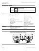
Figure 2. Acceptable Mounting Positions.
Allow eight inches (200 mm) headroom and six inches (150 mm) on either side of the
actuator.
For best performance, install the actuator vertically above the valve. The actuator can
be installed in any position between vertical and horizontal. Siemens Building
Technologies does not recommend installing the actuator below horizontal or up side
down. See Figure 2 for allowable mounting positions.
Complete instructions for field mounting the actuator are included with the actuator.
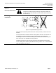
The “0” marking on the actuator yoke indicates stem up position. The “1” mark indicates
stem down position. See Figure 1.
AP0216R1
Siemens Building Technologies, Inc. Page 3