
Data Sheet for Product

SKD Electronic Valve Actuator 3-Position (Floating) Control Technical Instructions
Document No. 155-181P25
September 25, 2018
Siemens Industry, Inc. Page 5
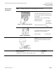
Operation,
Continued
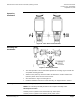
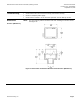
Figure 8. Valve Stem Travel Indication.
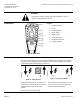
Mounting and
Installation
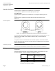
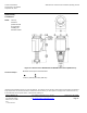
Figure 9. Mounting Positions.
• The vertical position is the recommended position for mounting. Figure 9 shows the
acceptable mounting positions.
• Allow 4 inches (100 mm) around the sides and back of the actuator and 8 inches
(200 mm) above and to the front of the actuator.
• See Dimensions in Figure 14 and Figure 15.
• Detailed installation instructions for field mounting are shipped with the actuator.
Start-Up
Check the wiring for proper connections.
NOTE: The valve body assembly determines the complete assembly action.
Normally Closed Valve
Actuator pressure cylinder moves outward (0 to 1): Valve opens.
Actuator pressure cylinder moves inward (1 to 0): Valve closes.