
Data Sheet for Product

Technical Instructions SKD Electronic Valve Actuator 3-Position (Floating) Control
Document No. 155-181P25
September 25, 2018
Page 8 Siemens Industry, Inc.
Wiring Diagrams,
Continued
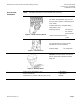
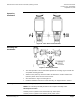
Spring Return
SKD82.51U
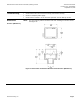
Figure 12. Spring Return Wiring Diagrams.
The diagram shows all possible connections. The application determines which
connections are used.
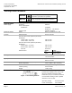
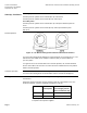
Connecting Terminals
G
System Potential 24 Vac (+)
21
System Neutral (SN)
Y1
Outward movement of the valve stem retainer (0 to 1)
Y2
Inward movement of the valve stem retainer (1 to 0)
Cm1
Limit switch for 100% stroke
c1
ASC9.3DU double auxiliary switch
c2
ASC9.3DU double auxiliary switch
1000
ASZ7.3 potentiometer
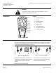
Accessory
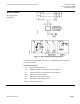
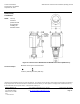
System neutral (SN) red
System potential (SP) black
24 Vac/30W
Figure 13. Heating Element ASZ6.6.