
Data Sheet for Product


SKD Electronic Valve Actuator 3-Position (Floating) Control Technical Instructions
Document No. 155-181P25
September 25, 2018
Siemens Industry, Inc. Page 7
Wiring Diagrams
Non-spring Return
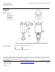
SKD82.50U
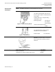
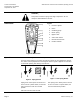
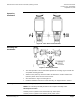
Figure 11. Non-spring Return Wiring Diagrams.
The diagram shows all possible connections. The application determines which
connections are used.
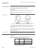
Connecting Terminals
G
System Potential 24 Vac (+)
Y1
Outward movement of the valve stem retainer (0 to 1)
Y2
Inward movement of the valve stem retainer (1 to 0)
Cm1
Limit switch for 100% stroke
C1
ASC9.3DU double auxiliary switch
C2
ASC9.3DU double auxiliary switch
1000
ASZ7.3 potentiometer