
Data Sheet for Product


Flowrite™ 8-inch Pneumatic Valve Actuator Technical Instructions
Document Number 155-161P25
June 14, 2019
Siemens Industry, Inc. Page 5
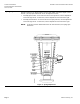
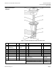
Parts of the 8-inch
Actuator
Figure 3. Flowrite AP 599 Series 8-inch Pneumatic Valve.
Item
Description
Qty
Material
Item
Description
Qty
Material
1
Upper housing
1
Aluminum
11
1/4-20 external tooth lock washer
2
Plated Steel
2
Diaphragm
(Normal duty)
(High temperature)
1
Neoprene
silicone
12
1/4-20 hex head cap screw
2
Plated Steel
3
3/8 x 24 hex nut
1
Plated steel
13
5/16-18 thread forming screws
6
Plated Steel
4
Piston plate
1
Aluminum
14
Spring
1
Chrome Van. Steel
5
Adjust. Screw Ass’y
1
Steel and bronze
15
Spring seat
1
Carbon Steel
6
Thrust washer
1
Carbon steel
16
Lower housing
1
Aluminum
7
Actuator shaft
1
Plated steel
17
Jam nut
1
Plated Steel
8
Stem adapter
1
Plated steel
18
Actuator retainer
1
Aluminum
9
Stem retainer clip
1
Stainless steel
Diaphragm replacement kit
Normal duty
High temperature
Item 2
599-01060
599-01061
10
Stem nut
1
Stainless steel
Stem retainer kit (One each of items 9 and 10)
599-10048
Stem adapter kit (items 8,9,10, and 17)
599-00435
Actuator retainer kit ( items 11, 12, and 18)
599-00436