
Data Sheet for Product


Flowrite VF599 Series Three-Way Valves Technical Instructions
2-1/2 to 6-inch Flanged Iron Body Document Number 155-160P25
June 14, 2019
Siemens Industry, Inc. Page 9
Dimensions
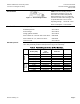
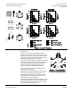
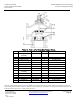
The letters in Figure 5 refer to actuator and service envelope dimensions in Table 11.
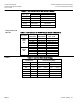
See Table 12 for valve body dimensions.
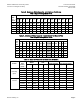
Table 11. Dimensions of the Actuator and Recommended Service Envelope.
Dimensions in Inches (Millimeters).
Figure 5.
Actuator
Actuator
Prefix
Code
Actual
Height of
Actuator
H1
Service
Height
H
Actual width or
diameter of
Actuator
W1
Service
Width
W
8" Pneumatic
277
278
283
284
14-1/8
(359)
26 (660)
8-3/4 (222)
diameter
21
(533)
12"
Pneumatic
279
281
285
287
17-7/8
(454)
30 (762)
15-1/8 (384)
diameter
27
(686)
SKB/C with
handle closed
289
290
291
292
293
294
14-3/4
(375)
22-3/4
(578)
7 (178) Width ×
8-15/16 (226)
Depth
25
(635)
SKD
267
274
275
276
11-13/16
(300)
19-3/4
(500)
5 (127) Width ×
6-5/8 (169)
Depth
14-1/2
(360)
Table 12. Valve Dimensions and Weight.
Nominal
Valve Size
Inches (mm)
Dimensions in Inches (Millimeters)
Weight
A
B
C
D
lbs. (kg)
ANSI
Class 125
ANSI Class
250
Service
Flange
ANSI Class
125
ANSI Class
250
2-1/2
(65)
10-7/8
(276.4)
11-1/2
(292)
9-3/8
(239.2)
3-3/4
(95)
6-1/2
(165)
50
(23)
63
(29)
3
(80)
11-3/4
(298.5)
12-1/2
(318)
10-3/4
(272)
4-3/8
(111)
7
(178)
65
(30)
82
(37)
4
(100)
13-7/8
(352.4)
14-1/2
(368)
12-1/2
(317.6)
5-1/8
(131.6)
7-1/2
(191)
110
(50)
134
(61)
5
(125)
15-3/4
(400)
16-5/8
(422)
13-3/4
(349.2)
5-3/4
(146.2)
8-1/2
(216)
136
(62)
176
(80)
6
(150)
17-3/4
(451)
18-5/8
(473)
15-1/2
(393)
6-5/8
(167)
9-1/2
(241)
141
(64)
258
(117)