
Data Sheet for Product


Flowrite™ 8-inch Pneumatic Valve Actuator Technical Instructions
Document Number 155-161P25
June 14, 2019
Siemens Industry, Inc. Page 3
Operation
The control air signal upon the diaphragm causes the valve to modulate whenever the air
pressure is within the spring range of the actuator. The actuator spring provides the
necessary force to hold the stem in the stem up (direct acting) position.
Mounting and
Installation
Allow 12 inches (300 mm) headroom and six inches (150 mm) on either side for
servicing the actuator.
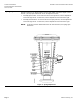
For best performance install the actuator vertically above the valve. The actuator may be
installed in any position between vertical and horizontal. Siemens Building Technologies
does not recommend installing the actuator below horizontal or up side down. See
Figure 1 for allowable mounting positions.
Complete instructions for field mounting the actuator are included with the actuator.
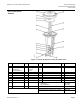
The top edge of the stem nut indicates the valve stem position. The “0” marking on the
actuator yoke indicates stem up position. The “1” mark indicates stem down position.
See Figure 2.
Figure 1. Acceptable Mounting Positions.
Service
Diaphragm
Replacement
Complete instructions are included in the diaphragm replacement kit.
WARNING:
Relieve spring tension before removing the actuator upper housing.