Technical Instructions Document No. 155-162P25 AP 599-2 June 14, 2019 Flowrite™ AP 599 Series 12-inch Pneumatic Valve Actuator Description The Flowrite™ AP 599 Series 12-inch pneumatic valve actuator is designed for use with the Flowrite VF 599 Series valves. This actuator is available with two stem strokes. Features • Completely enclosed actuator housing protects the diaphragm, springs, and start point adjuster. • Positioning relay is available factory-mounted or as an accessory.
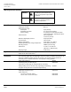
Flowrite™ AP 599 Series 12-inch Pneumatic Valve Actuator Technical Instructions Document No. 155-162P25 June 14, 2019 Warning/Caution Notations Specifications WARNING Personal injury or loss of life may occur if you not perform a procedure as specified. CAUTION Equipment damage, or loss of data may occur if you do not perform a procedure as specified.
Flowrite™ AP 599 Series 12-inch Pneumatic Valve Actuator Mounting and Installation Technical Instructions Document No. 155-162P25 June 14, 2019 Allow 12 inches (300 mm) above and 6 inches (150 mm) on each side of the actuator for servicing. For best performance, install the actuator vertically above the valve. The actuator may be installed in any position between vertical and horizontal. Siemens Building Technologies does not recommend installing the actuator below horizontal or upside down.
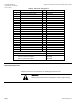
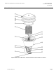
Flowrite™ AP 599 Series 12-inch Pneumatic Valve Actuator Technical Instructions Document No. 155-162P25 June 14, 2019 Table 2. Parts List. See Figure 2. Item Description 1 2 3 4 5 6 7 8 9 10 11 Qty 3/8-16 thread forming screw 16 Upper housing 1 Diaphragm 1 Piston plate 1 Spring 6 Anti-spin rod 2 Adjuster retaining ring 1 M20 × 1.
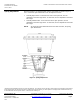
Flowrite™ AP 599 Series 12-inch Pneumatic Valve Actuator Technical Instructions Document No. 155-162P25 June 14, 2019 Parts of the Actuator Figure 2. Flowrite AP 599 Series 12-inch Pneumatic Valve Actuator. See Table 2. Siemens Industry, Inc.
Flowrite™ AP 599 Series 12-inch Pneumatic Valve Actuator Technical Instructions Document No. 155-162P25 June 14, 2019 Spring Adjustment With the actuator in an upright position and the stem visible as shown in Figure 3, use a 1-1/16 inch open-end wrench to turn the adjustment screw. • Normally Open Valves: To increase the start to close pressure, turn the adjustment screw from right to left. To decrease, turn the adjustment screw from left to right.