
Data Sheet for Product


Technical Instructions Flowrite™ AP 599 Series 12-inch Pneumatic Valve Actuator
Document No. 155-162P25
June 14, 2019
Page 4 Siemens Industry, Inc.
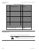
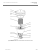
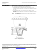
Table 2. Parts List. See Figure 2.
Item
Description
Qty
Material
1
3/8-16 thread forming screw
16
Plated Steel
2
Upper housing
1
Aluminum
3
Diaphragm
1
Buna-N
4
Piston plate
1
Aluminum
5
Spring
6
Chrome Silicon Steel
6
Anti-spin rod
2
Plated Steel
7
Adjuster retaining ring
1
8
M20 × 1.5 flat hex jam nut
1
Plated Steel
9
1/4-20 external tooth lock washer
2
Plated Steel
10
1/4-20 × 2-1/4 hex head cap screw
2
Plated Steel
11
Actuator shaft
1
3/4” (20 mm) stroke
Yellow Chromate Plated Steel
1-1/2” (40 mm) stroke
Bright Chromate Plated Steel
12
Start point adjuster
1
Brass
13
Spring plate
1
Aluminum
14
Lower housing
1
Aluminum
15
Stem retainer clip
1
Stainless Steel
16
Stem nut
1
Stainless Steel
17
Actuator retainer
1
Aluminum
18
Washer
6
—
19
#8 Thread forming screw
6
—
Retainer bracket kit — Items 9, 10 and 17
599-00436
Diaphragm replacement kit — Items 3, 18, and 19
599-01070
Stem retainer kit — Items 15 and 16
For 2-1/2 and 3 inch valves
For 4, 5, and 6-inch valves
599-10048
599-10049
Service
Diaphragm Replacement
Complete instructions are included in the diaphragm replacement kit.
WARNING:
Relieve spring tension before removing the actuator upper housing.