
Data Sheet for Product

Technical Instructions Flowrite VF 599 Series Two-Way Valves
Document Number 155-159P25 2-1/2 to 6-inch Flanged Iron Body
June 14, 2019
Page 8 Siemens Industry, Inc.
Operation
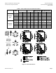
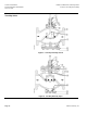
Figure 4 shows the normally open valve in the open or full flow position and the normally
closed valve in the closed or zero flow position. The actuator spring provides the necessary
force to hold the stem in the raised or normal position.
In the event of power failure, a spring return actuator returns the valve to its normal
position. Non-spring return actuators will hold the last commanded position. See the
Technical Instructions of the various actuators for additional information.
Normally Open Normally Closed
Figure 4. Operation.
Sizing
The sizing of a valve is important for correct system operation. An undersized valve will not
have sufficient capacity at maximum load. An oversized valve may initiate cycling, and the
seat and throttling plug may be damaged because of the restricted opening. Correct sizing
of the control valve for actual expected conditions is considered essential for good control.
Some variables which must be determined are:
• The medium to be controlled: steam, water, etc.
• The maximum inlet temperature and pressure of the medium at the valve.
• The pressure differential that will exist across the valve under maximum load demand.
• The maximum capacity the valve must deliver.
• The maximum line pressure differential that the valve actuator must close against.
See AB-1 Control Valve Selection and Sizing (Document Number 140-0038) for further
recommendations.
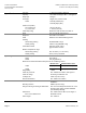
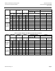
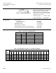
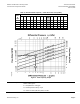
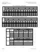
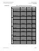
See Table 4 through Table 7, and Figure 2 for valve capacities.
Installation
• Install the valve so that the flow follows the direction of the arrow indicated on the valve
body identification tag.
• For best performance, install the valve assembly with the actuator above the valve
body. The valve and actuator can be installed in any position between vertical and
horizontal. It is not recommended to install the valve assembly below horizontal or
upside down.
• For flange dimensions and bolt hole information, see Cast Iron Flange Dimensions for
2-1/2 through 6” Valves Technical Bulletin (155-303P25 [TB 248]).
• Allow sufficient space for servicing the valve and actuator. See Table 14 for valve body
dimensions. See Table 13 and Figure 7 for dimensions of the service envelope
recommended around the actuator.
NOTE: Instructions for field mounting an actuator, spring adjustments, wiring diagrams,
and start-up are covered in the Technical Instructions and Installation Instructions
for each actuator.