
Data Sheet for Product


Technical Instructions Flowrite 599 Series SKB/C Electronic Valve Actuator Proportional Control
Document Number 155-163P25
September 25, 2018
Page 10 Siemens Industry, Inc.
Wiring Diagrams
The position output signal U will switch from 0 to 10 Vdc to 4 to 20 mA when a 4 to 20 mA
input signal is selected and used on the Y terminal.
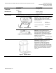
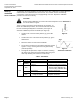
Figure 14. Connecting Terminals.
24 Vac
G
System potential (SP)
G0
System neutral (SN)
Y
Control input 0 to 10 Vdc or 4 to 20 mA
(DIP switch selectable)
Z
Override control
M
Measuring neutral
U
Output for 0 to 10 Vdc or 4 to 20 mA measuring
voltage. See Table 1.
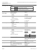
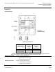
Table 1. Actuator Output Signal.
Actuator Input Signal
Receiving Impedance
Low (<500 ohm)
High (>10K ohm)
0 to 10 Vdc
0 to 20 mA
0 to 10 Vdc
4 to 20 mA
4 to 20 mA
2 to 10 Vdc
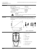
System neutral (SN) red
System potential (SP) black
24 Vac/30W
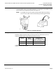
Figure 15.
Auxiliary Switch ASC1.6.
Figure 16.
Stem Heating Element
ASZ6.6.