
Data Sheet for Product


Technical Instructions Flowrite 599 Series SKB/C Electronic Valve Actuator Proportional Control
Document Number 155-163P25
September 25, 2018
Page 4 Siemens Industry, Inc.
Service Kits
Circuit board replacement 4 668 5748 8
Manual override kit 4268 5510 8
Plastic wiring compartment cover 4 104 5582 8
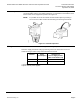
Stem retainer kit
Contains one stem nut (Figure 7, Item 6) and one stem retainer clip.
2-1/2 and 3-inch valves 599-10048
4, 5, and 6-inch valves 599-10049
Retainer clamp kit 599-10200
Ultraviolet (UV) resistant cable ties (pkg. of 8) 538-994
WARNING:
This product contains a spring under high compression. Do not attempt
to disassemble the actuator.
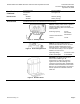
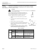
Operation
A 0 to 10 Vdc or a 4 to 20 mA control signal controls the actuator. The actuator,
mounted on a valve, produces a stroke proportional to the input signal. When power is
turned off or in the event of a power failure, the actuator spring returns the valve to its
normal position.
Figure 4. Input Signal.
Figure 5. Spring Return.
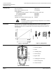
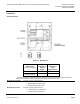
SKB/C Details
Figure 6. Actuator Design.
Legend
1. Pressure cylinder
2. Piston
3. Oscillating pump
4. Return springs
5. Bypass valve
6. Coupling piece (stem nut)
7. Manual setting knob
8. Position indicator