
Data Sheet for Product


Technical Bulletin 256 Flowrite 599 Series 2-1/2 to 6-Inch Valve, 2-Way & 3-Way and Actuator Assembly Selection
Document No. 155-776
December 26, 2017
Page 2 Siemens Industry, Inc.
Selection Example Specification
Select a two-way normally closed valve and actuator assembly for an ANSI 125 piping
system that will deliver 500 gpm (113 m
3
/
h) chilled water with an equal percentage flow
characteristic with no more than 5 psi (35 kPa) pressure drop across the fully open
valve.
The valve shall be operated by a 24 Vac powered, 0 to 10 Vdc control signal, spring
return electronic actuator, and must close off tightly against a pump head pressure of
15 psi (1 bar).
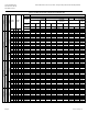
Valve Sizing
Use Figure 1, the water capacity graph, to begin valve sizing.
1. Locate 500 gpm (113 m
3
/h) on the vertical axis to find the required flow.
2. Read across the horizontal axis to find 5 psi (35 kPa), the maximum allowable
pressure drop across the open valve.
3. Select a 5-inch (125 mm) 250 Cv (214 Kvs) line size valve because the point of
intersection falls close to the 5-inch line.
Actuator selection
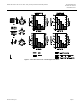
Use Figures 2, the close-off pressure graph, to choose an actuator.
1. Locate the graph for electronic actuators for NC valves in the upper left side of the
figure.
2. Locate the bar for 5-inch valves. The black bar represents an SKB/C actuator.
3. Notice that the SKB/C has the sufficient force to provide tight close-off against
more than 20 psi (1.4 bar) differential. For a 5-inch valve, select an SKC actuator
with a 40 mm stroke.