Technical Instructions Document No. 155-541P25 October 15, 2018 Flowrite™ 599 Series Rack & Pinion Valves Description Features The Flowrite 599 Series Rack & Pinion Valve couples the OpenAir™ Actuator to a 1/2to 2-inch Flowrite 599 Series two- or three-way valve via a linkage. The linkage transforms the actuator rotary movement into the linear motion required to position the valve.
Technical Instructions Document No. 155-541P25 October 15, 2018 Product Numbers Flowrite 599 Series Rack & Pinion Valves Table 1 provides a complete description of the product numbers. Table 1. Flowrite 599 Series Rack & Pinion Valve Product Numbers. Product Number Description 298-XXXXX Assembly consisting of: OpenAir Electronic Actuator, linkage, and 1/2299-XXXXX inch to 2-inch Flowrite two-way or three-way valve body. 298-XXXXX includes: OpenAir GCA161.
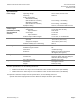
FlowriteTM 599 Series Rack & Pinion Valves Technical Instructions Document No. 155-541P25 October 15, 2018 Specifications Power supply Operating voltage Frequency Power consumption 599-03609 assembly (with GCA161.1U actuator) 599-03611 assembly (with GCA121.1U actuator) Equipment rating 24 Vac ±20%, 24 Vdc ±10% 50/60 Hz 9 VA running, 5 VA holding 8 VA running, 3 VA holding Class 2, in accordance with UL/CSA Input signal voltage input input resistance current input input resistance 0 to 10 Vdc (max.
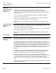
Technical Instructions Document No. 155-541P25 October 15, 2018 Flowrite 599 Series Rack & Pinion Valves Operation 599-03609 assembly with GCA161.1U actuator A continuous 0 to 10 Vdc signal from a controller to Terminal Y (8, gray) of a normally-closed, direct-acting assembly operates the actuator and the valve opens respectively. The linkage proportionally translates the rotary actuator stroke into a linear valve stem motion.
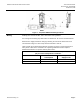
FlowriteTM 599 Series Rack & Pinion Valves Technical Instructions Document No. 155-541P25 October 15, 2018 Figure 1. Acceptable NEMA 2 Mounting Positions. Wiring All wiring must conform to NEC, and to local codes and regulations. Use earth ground isolating step-down Class 2 transformers. Do not use autotransformers. Determine the supply transformer rating by summing the total VA of all actuators used. The maximum rating for a Class 2 step-down transformer is 100 VA.
Technical Instructions Document No. 155-541P25 October 15, 2018 Flowrite 599 Series Rack & Pinion Valves Wiring Diagrams 599-03609 assembly with GCA161.1U actuator Table 3. 599-03609 Assembly (with GCA161.1U) for Modulating Control with 24 Vac or 24 Vdc Supply Voltage.
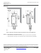
Technical Instructions Document No. 155-541P25 October 15, 2018 Flowrite 599 Series Rack & Pinion Valves Dimensions Figure 2. Dimensions of the Flowrite 599 Series Rack & Pinion Valve in Inches (Millimeters).