
Data Sheet for Product

Technical Instructions Flowrite 599 Series Rack & Pinion Valves
Document No. 155-541P25
October 15, 2018
Page 6 Siemens Industry, Inc.
Wiring Diagrams
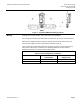
599-03609 assembly
with GCA161.1U
actuator
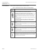
Table 3. 599-03609 Assembly (with GCA161.1U) for Modulating Control with 24 Vac or 24 Vdc
Supply Voltage.
Standard
Symbol
Function
Terminal
Connection
Standard
Color
1
Supply (SP)
G
Red
2
Neutral (SN)
G0
Black
8
0 to 10 Vdc input signal
Y
Gray
9
Output for 0 to 10 Vdc
position feedback indication
U
Pink
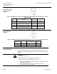
599-03611 assembly
with GCA121.1U
actuator
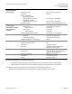
Table 4. 599-03611 Assembly (with GCA121.1U) for 24 Vac or 24 Vdc Two-Position Control.
Standard
Symbol
Function
Terminal
Connection
Standard
Color
1
Supply (SP)
G
Red
2
Neutral (SN)
G0
Black
Start Up/
Commissioning
• Check that the wires are connected correctly.
• For additional actuator information, see OpenAir™ GCA Series Spring
Return 142 lb-in Electronic Damper Actuators Technical Instructions (155-
173P25).
Service
WARNING:
Do not open the actuator.
If the linkage or actuator is inoperative, replace the unit.
For valve service kits, see the following documents:
• Flowrite 599 Series Two-Way 1/2 to 2-Inch Bronze Valves Technical
Instructions (155-184P25)
• Flowrite 599 Series Three-Way 1/2 to 2-inch Bronze Valves
Technical Instructions (155-185P25)