Technical Instructions Document No. 155-032P25 AP 331-2 November 10, 2021 POWERS™ CONTROLS No. 4 Pneumatic Damper Actuator Actuator Assembly 331-2929 Typical Actuator Assembly 331-2904 Typical Actuator Assembly 331-3000 Typical Description The Powers Controls No. 4 Pneumatic Damper Actuator is a totally enclosed pneumatic piston type actuator designed to operate dampers for ventilating systems, mixing box control, and other applications requiring a large, effective diaphragm area and long stroke.
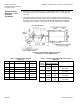
Technical Instructions Document Number 155-032P25 November 10, 2021 POWERS™ CONTROLS No. 4 Pneumatic Damper Actuator Warning/Caution Notations WARNING: Personal injury, or loss of life may occur if you do not follow a procedure as specified. CAUTION: Equipment damage, or loss of data may occur if you do not follow a procedure as specified. Table 1. Product Numbers for No. 4 Pneumatic Damper Actuator.
POWERS™ CONTROLS No.
Technical Instructions Document Number 155-032P25 November 10, 2021 Accessories Page 4 POWERS™ CONTROLS No.
POWERS™ CONTROLS No. 4 Pneumatic Damper Actuator Service Kit EPDM diaphragms (package of 5) Technical Instructions Document Number 155-032P25 November 10, 2021 333-071 Figure 1. Actuator Jam Nut Location. WARNING: Do not remove the jam nut (Figure 1). Spring is under heavy load. Repair by trained personnel only. Actuator Selection for Unit Ventilator For specific unit ventilators, see Application Bulletins found in Section 36 of the POWERS™ Controls Installed Applications Manual (144-004).
Technical Instructions Document Number 155-032P25 November 10, 2021 Operation POWERS™ CONTROLS No. 4 Pneumatic Damper Actuator The air tubing from a controlling instrument connects to the actuator's upper housing. With no control pressure to the actuator, the compression spring forces the diaphragm and actuator shaft toward the upper housing, but is limited by the jam nut on the actuator shaft.
POWERS™ CONTROLS No. 4 Pneumatic Damper Actuator Technical Instructions Document Number 155-032P25 November 10, 2021 Hesitation Actuator Example: Adjustment To obtain an initial hesitation point after one inch (25 mm) of shaft travel. 1. Add air pressure to the actuator until shaft travel is one inch (25 mm). 2. Turn locknuts on cycle adjustment rods until they contact lower housing, then lock together (Figure 4, Items 10 and 11).
Technical Instructions Document Number 155-032P25 November 10, 2021 Extended Shaft Mounting - Pivot Actuator, Continued POWERS™ CONTROLS No. 4 Pneumatic Damper Actuator 3. Slip the crank over the 3/8 through 1/2-inch (10 through 13-mm) diameter damper shaft (Figure 6).
POWERS™ CONTROLS No. 4 Pneumatic Damper Actuator Extended Shaft Mounting - Fixed Actuator Technical Instructions Document Number 155-032P25 November 10, 2021 1. Order one of the following damper actuators, the clevis, and linkage kit (Figure 8): Actuator with mounting bracket: 331-2927 or 331-2974 Clevis: 331-801 Linkage Kit: 331-958 2. Determine the application, and select appropriate "X" and "Y" dimensions from Table 7.
Technical Instructions Document Number 155-032P25 November 10, 2021 Extended Shaft Mounting - Fixed Actuator, Continued POWERS™ CONTROLS No. 4 Pneumatic Damper Actuator 4. Place the front of the actuator on the "X" dimension line so the actuator shaft faces the damper shaft. Place the centerline of the actuator over the "Y" dimension line (Figure 8). 5. Thread Clevis 331-801 onto the actuator shaft and tighten it against the lock nut.
POWERS™ CONTROLS No. 4 Pneumatic Damper Actuator Frame Mounting Technical Instructions Document Number 155-032P25 November 10, 2021 1. Order one each of the following: Actuator assembly: 331-3000, 331-3001, 331-3002, 331-2973, or 331-3004 2. Weld the mounting lug to the damper frame (Figure 10) so that it is parallel and 5/16-inch (8 mm) from the inside edge of the damper frame and perpendicular to it. Weld the mounting lug along both sides.
Technical Instructions Document Number 155-032P25 November 10, 2021 POWERS™ CONTROLS No. 4 Pneumatic Damper Actuator Dimensions Figure 10. Frame Mounting Dimensions. Dimensions in Inches (Millimeters). Figure 11. Mounting Bracket Dimensions. Dimensions in Inches (Millimeters). Page 12 Siemens Industry, Inc.
POWERS™ CONTROLS No. 4 Pneumatic Damper Actuator Technical Instructions Document Number 155-032P25 November 10, 2021 Dimensions, Continued Figure 12. Actuator Mounting Plate 331-623, 1/4-Inch (6 mm) Thick. Dimensions in Inches (Millimeters). Figure 13. Frame Mounting Normally Open Damper. Table 8. Mounting Plate Hole Designations (Figure 12). Hole Description 1 No. 6 actuator extended shaft mounting 2 Not used 3 No. 4 actuator extended shaft No. 6 actuator frame mounting NC 4 No.
Technical Instructions Document Number 155-032P25 November 10, 2021 POWERS™ CONTROLS No. 4 Pneumatic Damper Actuator Dimensions, Continued Figure 16. Bracket Mounted Actuator (Typical). Dimensions in Inches (Millimeters). Table 9. Stop Screw Adjustment and Stroke Length (Figure 16). Stop Screw Stroke Length Adjustment Inches (Millimeters) Dimension "A" Kit 331-938 Kit 331-939 Inches (Millimeters) IN 0 3.0 (76) 2-3/8 (60) 0.5 (13) 3.5 (89) 2-7/8 (73) 1.0 (25) 4.0 (102) 3-3/8 (85) 1.5 (38) 4.