
Data Sheet for Product


POWERS™ CONTROLS No. 4 Pneumatic Damper Actuator Technical Instructions
Document Number 155-032P25
November 10, 2021
Siemens Industry, Inc. Page 7
Hesitation Actuator
Adjustment
Example:
To obtain an initial hesitation point after one inch (25 mm) of shaft travel.
1. Add air pressure to the actuator until shaft travel is one inch (25 mm).
2. Turn locknuts on cycle adjustment rods until they contact lower housing, then lock
together (Figure 4, Items 10 and 11). For initial hesitation point settings other than
one inch (25 mm), follow this same procedure.
CAUTION:
Make certain cycle adjustment nuts are even to ensure smooth operation.
Extended Shaft
Mounting - Pivot
Actuator
1. Order one of the following for extended shaft mounting. These assemblies are
designed for 90° damper rotation.
Actuator: 331-3000, 331-3001, 331-3002, 331-2973, or 331-3004
NOTE: Clevis mounts in Crank Radius Hole No. 1 for 90° damper rotation.
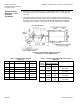
2. Slip the 3/4-inch (19 mm) diameter hole in the mounting plate over the damper shaft
(Figure 5).
Figure 5. Actuator Mounting Plate 331-623.
Dimensions in Inches (Millimeters).
Table 4. Mounting Plate Hole Identification.
Hole
Used For
1
No. 6 Actuator extended shaft mounting
2
Not used
3
No. 4 Actuator extended shaft
No. 6 Actuator frame mounting NC
4
No. 6 Actuator frame mounting NO
5
No. 4 Actuator frame mounting NC
6
No. 4 Actuator frame mounting NO