
Data Sheet for Product


POWERS™ CONTROLS No. 4 Pneumatic Damper Actuator Technical Instructions
Document Number 155-032P25
November 10, 2021
Siemens Industry, Inc. Page 9
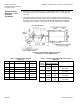
Extended Shaft
Mounting - Fixed
Actuator
1. Order one of the following damper actuators, the clevis, and linkage kit (Figure 8):
Actuator with mounting bracket: 331-2927 or 331-2974
Clevis: 331-801
Linkage Kit: 331-958
2. Determine the application, and select appropriate "X" and "Y" dimensions from
Table 7. Select a rigid section of the duct, if possible, and then draw these lines on
the duct.
NOTE: If the "X" dimension is 8-1/2 inches (216 mm), place the rear of the
actuator against the damper shaft and draw a line along the front of the
bracket for the "X" dimension. Measure the “Y” dimension.
3. If the actuator assembly mounts to the right of the damper shaft (Figure 8):
• Draw the "Y" dimension line above the damper shaft if the damper blade is to
rotate CCW as actuator pressure increases.
• Draw the "Y" line below the damper shaft if the damper blade is to rotate CW as
actuator pressure increases.
If the actuator assembly mounts to the left of the damper shaft:
• Draw the "Y" dimension line above the shaft if the damper blade is to rotate CW
as actuator pressure increases.
• Draw the "Y" line below the damper shaft if the damper blade is to rotate CCW as
actuator pressure increases.
CAUTION:
It is important to use the "X" and "Y" dimensions in Table 7 to position the
actuator. They were selected to ensure that the crank is approximately
perpendicular to the actuator shaft at half its stroke. This will prevent the
linkage from scissoring or locking up (see Figure 7).
Figure 7. Perpendicular Mounting.