
Product Overview
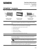


POWERS™ Controls No. 4 Pneumatic Damper Actuator Technical Instructions
Document Number 155-032P25
October 10, 2005
Siemens Building Technologies, Inc. Page 5
Service Kit
EPDM diaphragms (package of 5) 333-071
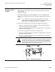
Figure 1. Actuator Jam Nut Location.
WARNING:
Do not remove the jam nut (Figure 1). Spring is under heavy load.
Repair by trained personnel only.
Actuator Selection
for Unit Ventilator
For specific unit ventilators, see Application Bulletins found in Section 36 of the
POWERS™ Controls Installed Applications Manual (144-004).
Actuator Sizing
The quantity of actuators required depends on several torque factors. To determine the
quantity of actuators required for the installation:
1. Obtain damper torque ratings (ft-lb/ft
2
) from the damper manufacturer.
2. Determine the area of the damper.
3. Calculate the total torque required to move the damper:
Total Torque = Torque Rating × Damper Area
4. Calculate the total quantity of actuators required:
Number of Total Damper Torque Required
Actuators
=
SF
1
× Actuator Torque (Table 2)
1
Safety Factor: When calculating the number of actuators required, a safety factor
should be included for unaccountable variables such as slight misalignments, aging of
the damper, etc. A suggested safety factor is 0.80 (or 80% of the rated torque).
See AB-300 Damper Actuator Sizing and Selection Application Bulletin in the HVAC
Systems/Controls Reference Data (125-1853) for additional sizing information. See
TB-181 POWERS™ Controls Maximum Thrust Ratings of Pneumatic Damper Actuators
Technical Bulletin (155-219P25) for additional torque requirements.
Figure 2. Hesitation Actuator Adjustment.