
Product Overview


Technical Instructions POWERS™ Controls No. 4 Pneumatic Damper Actuator
Document Number 155-032P25
October 10, 2005
Page 8 Siemens Building Technologies, Inc.
Extended Shaft
Mounting - Pivot
Actuator,
Continued
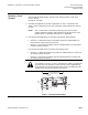
3. Slip the crank over the 3/8 through 1/2-inch (10 through 13-mm) diameter damper
shaft (Figure 6).
With the actuator assembly to the left of the damper shaft, an increase in actuator
pressure rotates the damper blade clockwise (CW) when the crank is above the
damper shaft (Figure 6), or counterclockwise (CCW) when the crank is below the
damper shaft.
Figure 6. Actuator 331-3000 (Typical).
With the actuator assembly to the right of the damper shaft, an increase in actuator
pressure rotates the damper blade CCW when the crank is above the damper shaft,
or CW when the crank is below the damper shaft.
4. Position the mounting plate and attach it to the duct with four screws.
Table 5. Actuator Accessories Shown in Figure 6.
Item Part No. Description Qty. Material
1 331-565 Pivot shaft 1 Steel
2 047-061J E-ring 2 Steel
3 146-020K Lock washer 1 Steel
4 041-162J Nut 1 Steel
5 041-142 Nut 1 Steel
6 333-207 Clevis 1 Zinc plated steel
7 331-807 Hitch pin 1 Zinc plated steel
8 331-293 Clevis pin 1 Zinc plated steel
9 331-923 Crank assembly 1 Galvanized steel
10 331-623 Actuator mounting plate 1 Steel
— 034-283 Mounting screws 4 Steel
F 333-034 Rocker — Zinc plated steel
F 331-801 Clevis 1 Steel-reinforced plastic
F 034-123K Mounting screws 3 Steel
F 041-230J Nut 2 Steel
F 030-510J Screws 2 Steel
"F" Parts for Frame Mounting.