
Product Overview


Technical Instructions POWERS™ Controls No. 6 Pneumatic Damper Actuator
Document No. 155-029P25
December 3, 2004
Page 8 Siemens Industry, Inc.
Frame Mounting -
Type A,
Continued
Two-Section Damper
Kit 752
See Figure 6 and
Figure 7
1. Follow the steps in One-Section Damper.
2. Attach the Damper Blade Clip to the damper blade in the second damper section.
Repeat Step 2 in One-Section Damper. The push rod will connect to the extra crank
on the drive shaft.
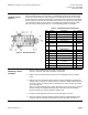
Figure 6. Two-section Damper.
Figure 7. Actuator and Clevis Assembly 331-2857 (Typical)
Attached to Frame Mounting Kit 752.
Dimensions in Inches (Millimeters).