
Data Sheet for Product

599 Series Zone Valve 2-way, 3-way Thermic Actuators Technical Instructions
Document Number 155-780
May 19, 2017
Siemens Industry, Inc. Page 5
Mounting and
Installation Notes,
Continued
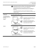
1. Disconnect the connection cable.
2. Wait six minutes until the actuator is cooled down.
3. Turn the actuator bayonet ring counter-clockwise for two clicks, to the end position.
4. Lift the actuator off the valve.
When dismounted, the actuator will be set automatically to the original position (factory
setting).
NOTE: Occasionally, the actuator may be released from the valve together with the
bayonet nut stuck in the actuator. To re-use the actuator, the actuator's stem
must be reset to the original position (factory setting). To reset the stem, turn
the actuator upside down and push the stem while simultaneously turning the
bayonet ring counter-clockwise until it latches.
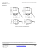
Mounting Positions
Actuators may be installed in any position (360°).
Maintenance
The actuator is maintenance-free.
WARNING:
Disconnect the connecting cable from the operating voltage prior to
replacing. Opening the actuator can cause irreparable damage. It may also
result in injury from the strong, installed spring.
Electrical
Installation
• Observe all local installation regulations.
• Install the connecting cable downwards so that it leads away from the actuator.
• Isolate the power supply. (For example, connect an automatic circuit breaker or
switch fuse upstream of the control unit.)
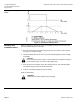
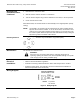
Wiring Diagram
NOTE: G: positive
G0: neutral
Figure 4. Wiring Diagram.