
Data Sheet for Product


Technical Instructions SAS Electronic Valve Actuator, 24V, Floating (3-Position) Control
Document Number 155-681
October 2, 2017
Page 4 Siemens Industry, Inc.
Wiring Diagrams
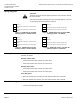
CAUTION:
Terminals G and G0 must be properly wired for correct function and full
life of the actuator.
If the actuator makes a buzzing noise upon reaching setpoint, G and G0
are improperly wired and should be reversed.
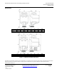
G
Hot (+) G Neutral (-)
Y1
Connected to Neutral (-) extends actuator
stem
Y1 Connected to Hot (+) extends actuator stem
Y2
Connected to Neutral (-) retracts actuator
stem
Y2 Connected to Hot (+) retracts actuator stem
Figure 2. SAS81.03U 24 Vac NSR Figure 3. SAS81.03U 24 Vac or 24 Vdc NSR
Floating Control - Neutral Switch. Floating Control - Hot Switch.
G
Hot (+) G Hot (+)
G0
Neutral (-) G0 Neutral (-)
Y1
Connected to Neutral (-) extends actuator
stem
Y1 Connected to Hot (+) extends actuator stem
Y2
Connected to Neutral (-) retracts actuator
stem
Y2 Connected to Hot (+) retracts actuator stem
Figure 4. SAS81.33U 24 Vac SR Figure 5. SAS81.33U 24 Vac or 24 Vdc SR
Floating Control – Neutral Switch. Floating Control – Hot Switch.
Start-Up
The valve body assembly determines the action of the complete valve/actuator
assembly as follows:
Normally Closed Valve:
• When the actuator stem extends, the valve opens.
• When the actuator stem retracts, the valve closes.
Normally Open Valve:
• When the actuator stem extends, the valve closes.
• When the actuator stem retracts, the valve opens.
Three-Way Valve:
• When the actuator stem extends, the valve opens between port A and AB.
• When the actuator stem retracts, the valve opens between port B and AB.
Troubleshooting
• Check wiring for proper connections and secure attachments.
• Check for adequate power supply.