
Data Sheet for Product
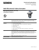

Technical Instructions SAX Electronic Valve Actuator
Document Number 155-507 Non-spring Return, 24 Vac 3-position (Floating) Control
June 15, 2016
Page 4 Siemens Industry, Inc.
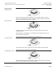
Components
A
Manual adjuster (with slide switch)
B
Wiring knockouts
C
Position indication
D
Status indication (SAX61.03U only)
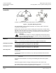
E
Housing cover
F
Valve stem coupling
G
Yoke
H
Valve neck coupling
Operation
The actuator accepts a 24 Vac control signal to Y1, which causes the actuator’s stem
retainer to move toward the valve (extend). A 24 Vac control signal to Y2 causes the
actuator’s stem retainer to move toward the actuator (retract). The stroke travel is
proportional to the length of time the signal is applied.
When power is turned off or in the event of a power failure, the actuator maintains its
position.
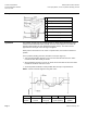
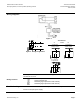
In the 3-position (floating) actuators, deviation occurs (See Figure 1):
after several positioning signals Y1 and Y2 in the same direction since the stroke
movement starts with a delay of 300 ms.
when positioning signals Y1 and Y2 are active for less than 300 ms since the stroke
movement cannot be made in that case.
Accurate position feedback is made possible with the help of a potentiometer.
NOTE: Consult Technical Support if using with a TEC.
A
B
C
Y1
Y2
0
Calculated
position
Actual
position
Positioning
time [ms]
Positioning signals
(power applied)
No power
applied
Figure 1. Three-position (Floating) Actuator Deviation.