
Installation Instructions


Document No. 129-571
Installation Instructions
June 15, 2016
Page 4 of 8 Siemens Industry, Inc.
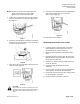
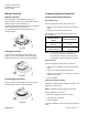
Figure 11. SAV Actuator with Cover
Removed.
A
Plug-in space for…
Potentiometer ASZ7.5.. (SAV81.00U only) or
Auxiliary switch ASC10.51.
B
Plug-in space for…
Function module AZX61.1 (SAV61.00U only), or
Auxiliary switch ASC10.51
C
LED (SAV61.00U only)
D
DIP Switches (SAV61.00U only)
E
Calibration Slot (SAV61.00U only)
F
Connection Terminals
Wiring
NOTE: All wiring must conform to national and local
codes and regulations (NEC, CE, and so on).
Do not use autotransformers. Use earth ground
isolating step-down Class 2 power supply
transformers.
Determine supply transformer rating by summing total
VA of all actuators used. The maximum rating for a
Class 2 step-down transformer is 100 VA.
It is recommended that no more than 10 actuators are
powered by one transformer.
Parallel Control of Actuators
SAV81.00U - Three-position actuators must have their
own specific controller.
SAV61.00U - Up to 10 actuators can be driven in
parallel from a single controller output with a rating of
1 mA. Modulating actuators have an input impedance
of 100KΩ.
NOTE: Use either a Phillips head screwdriver or a flat-
blade screwdriver to remove the wiring
compartment housing cover for access to the
terminal block and DIP switches.
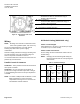
DIP Switch Setting (SAV61.00U only)
Switch 1: Control Signal
Select between 0 to 10 Vdc or 4 to 20 mA input signal
for terminal Y (0 to 10 Vdc default).
Switch 2: Flow Characteristic
Do not change the flow characteristic switch from the
default setting.
NOTE: Changing the default setting will modify the
linear flow characteristic to: fast opening flow
characteristic
Table 1. DIP Switch Settings.
Position
Positioning
Signal
"Y"
Position
Feedback
"U"
Flow Characteristic
OFF
1)
0 to 10
Vdc
0 to 10
Vdc
Default =
Linear
ON
DC 4 to
20 mA
0 to 10
Vdc
Modified =
Fast
Opening
1) Factory setting: All DIP switches are set to OFF.