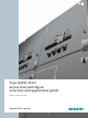
Type GM38 38 kV metal-clad switchgear selection and application guide E50001-F710-A124-X-4A00 Answers for energy.
Table of contents Overview 4–6 Construction 7–12 Accessories 13 Protective relays 14 Vacuum circuit breakers 15–21 Technical data 22–25 Dimensions 26–29 Side views 30 Notes 31
Type GM38 Medium-voltage metal-clad switchgear Siemens’ experience gained in over 80 years of supplying metal-clad switchgear in the U.S. has been captured in the type GM38 design. The objective has been to incorporate features designed to provide safety, while simplifying operation and maintenance, as well as minimizing installation cost. Type GM38 switchgear is designed for use in industrial plants, commercial buildings, electric utility systems, cogeneration installations and other electrical systems.
Overview Siemens type GM38 38 kV metal-clad power switchgear assemblies with horizontal drawout type 38-3AH3 vacuum circuit breakers take advantage of the latest developments in vacuum interrupter technology. Voltage transformers (VTs) with their associated drawout primary fuses can be located in the cell above a 1,200 A or 2,000 A circuit breaker, allowing significant space savings. Siemens introduced this feature to the 38 kV switchgear market with the launch of the type GM38 design in 1993.
Overview “Universal” spare circuit breaker Full ANSI design background The physical configuration and interlock logic allow the use of a single circuit breaker to serve as a “universal” spare circuit breaker at an installation site.
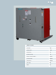
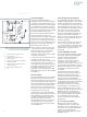
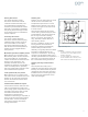
Overview 1 3 2 6 7 8 5 4 8 Figure 2: Circuit breaker cell (1,200 A or 2,000 A) with VT auxiliary (3,000 A similar except upper cell reserved for fan-cooling equipment) 1. 2. 3. 4. 5. 6. 7. 8. Drawout primary CL fuses for VTs VTs (stationary) Upper door for protective relays, instruments, etc.
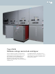
Construction Switchgear compartments Bus compartment Vacuum circuit breaker cell The bus compartment is a separately enclosed space for three-phase insulated main power bus bars, supports and connections to circuit breaker cells. The circuit breaker cell is a bolted, reinforced sheet steel enclosure, with provisions for a type 38-3AH3 vacuum circuit breaker.
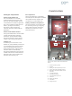
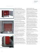
Construction Circuit breaker cell features Vacuum circuit breaker cell Figure 4: Circuit breaker being racked out with door closed A circuit breaker cell consists of a bolted, reinforced sheet steel enclosure, with provisions for a type 38-3AH3 vacuum circuit breaker. The cell includes a blank hinged front door, inter-compartment and inter-unit barriers, stationary primary and secondary disconnects, automatic shutters, drawout guide rails, circuit breaker racking mechanism and necessary interlocks.
Construction Primary disconnects Auxiliary cells The cubicle stationary primary disconnect contacts are recessed inside the insulator assemblies, and are located behind grounded steel shutters to prevent accidental contact when the circuit breaker is withdrawn. The primary disconnect finger clusters are mounted on the circuit breaker for ease of inspection. Auxiliary cells are constructed in a similar manner as the circuit breaker cells, except without provisions for a circuit breaker element.
Construction Figure 7: Primary CL fuses accessible when fuse truck in disconnect position and access door open Voltage transformers (VTs) Current transformers (CTs) Up to three VTs with their drawout mounted current limiting fuses may be mounted in an auxiliary cell. VTs can be accommodated in the upper cell above a circuit breaker, or in either the upper or lower cells of a section that does not have a circuit breaker cell.
Construction Bus bar insulation Wiring Bus bars are insulated using heat-shrink insulation. Bolted bus joints are insulated by pre-formed molded boots, which are held in place by nylon hardware. For bus configurations where no boot design is available, taped joints are used. The main bus is supported with cycloaliphatic epoxy inserts where the bus passes from one section to another. Other bus is supported using porcelain standoff insulators.
Construction Instrumentation and protective relays Shelter-Clad design – single aisle Instruments, meters and protective relays can be traditional switchboard type or modern electronic type, depending on the requirements of the specification. If traditional electromechanical devices are used, they have semi-flush cases with dull black covers. Indicating and recording instruments, meters and protective relays are of the rectangular type, semi-flush mounted.
Accessories Standard accessories include: Manual racking crank Manual spring charging crank Drawout extension rails (facilitate handling of circuit breakers in outdoor non-walk-in switchgear or drawout fuse trucks when located above floor level) Lifting sling (for circuit breakers or drawout fuse trucks located above floor level) Split plug jumper (standard unless test cabinet is furnished) Contact lubricant Touch up paint.
Protective relays SIPROTEC™ System advantages one bay, one unit SIPROTEC has established itself across the market as the standard for numerical protective relaying. Besides the common system platform and the unique type DIGSI 4 service interface that may be used for all protective devices, it also supports the new IEC 61850 communication standard. The type SIPROTEC 4 protective relay family offers fully integrated protection, control, monitoring and automation functions incorporated in a single device.
Vacuum circuit breakers Type 38-3AH3 vacuum circuit breakers Floor rollout Siemens type 38-3AH3 circuit breakers are available in 31.5 kA through 40 kA interrupting classes, or 1,500 MVA on the older “constant MVA” rating basis. Continuous current ratings include 1,200 A and 2,000 A self-cooled and 3,000 A forced-air cooled. The circuit breakers are arranged to rollout directly on the floor in front of the switchgear, if the indoor switchgear is not located on a “housekeeping” pad.
Vacuum circuit breakers 1 2 3 4 Manual controls and indicators Trip-free design All circuit breaker manual controls and indicators are conveniently located on the front of the circuit breaker. Standard features include manual close button, manual trip button, open-close indicator, stored-energy closing spring charge/ discharge indicator, manual springcharging access port and close operation counter. The operating mechanism conforms to the trip-free requirements of ANSI/IEEE standards.
Vacuum circuit breakers 16 1 3 13 4 5 8 2 17 18 7 9 6 14 15 19 10 1. 2. 3. 4. 5. 6. 7. 8. 9. Gearbox Closing spring Opening spring Jack shaft Auxiliary switch MOC switch operator Spring charging motor (behind limit switches) Push-to-close Push-to-trip 10. 11. 12. 13. 14. 15. 16. 17. 18. 19.
Vacuum circuit breakers Non-sliding current transfer “Universal” spare circuit breaker The vacuum interrupter movable stem is connected to the lower disconnect stab of the circuit breaker by a reliable flexible connector, a method pioneered by Siemens in the 1970s. This provides a low-resistance current transfer path, not subject to the wear and contamination problems associated with sliding or rolling joints used in some designs.
Vacuum circuit breakers Auxiliary switch (circuit breaker mounted) The auxiliary switch assembly is mounted on the vacuum circuit breaker with contacts for use in the circuit breaker control circuit and as spare contacts for other use. Normally, four auxiliary switch contacts, two NO (52a) and two NC (52b) can be wired out for purchaser use. Mechanism operated cell (MOC) switch When required, 6, 12, 18 or 24 stages of MOC auxiliary switch can be mounted in the circuit breaker cell.
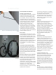
Vacuum circuit breakers g Low current chopping characteristics The chrome-copper contact material used in Siemens vacuum interrupters limits chopping currents to a maximum of 5 A. This low value prevents the build-up of unduly high voltages and results in lower stress on the insulation of load equipment.
Vacuum circuit breakers Vacuum interrupter principles With Siemens type 38-3AH3 vacuum circuit breakers, the chopping currents are held to 5 A or less. This is low enough to prevent the build-up of unduly high voltages, which may occur on switching of inductive circuits. The chrome-copper contact material keeps overvoltages to a minimum, so special surge protection is not required in most applications.
Technical data These ratings are in accordance with the following standards: g ANSI/IEEE C37.04-1999 Standard Rating Structure for AC High-Voltage Circuit Breakers g ANSI C37.06-2009 AC High-Voltage Circuit Breakers Rated on a Symmetrical Current Basis – Preferred Ratings and Related Required Capabilities Circuit breaker type1 Rated values Maximum design voltage (V)2 Units 38-3AH3-31 38-3AH3-40 kV rms 38.0 38.0 ---- 1.0 1.
Technical data These ratings are in accordance with the following standards: g ANSI/IEEE C37.04-1979 Standard Rating Structure for AC High-Voltage Circuit Breakers Rated on a Symmetrical Current Basis g ANSI C37.06-1987 AC High-Voltage Circuit Breakers Rated on a Symmetrical Current Basis – Preferred Ratings and Related Required Capabilities ANSI/IEEE C37.09-1979 Standard Test Procedure for AC High-Voltage Circuit Breakers Rated on a Symmetrical Current Basis g ANSI/IEEE C37.
Technical data Control voltages, ANSI C37.06 Close coil Trip coil Spring charging motor Range Run (avg.) Inrush (peak) Charging Nominal Close Trip A1 A1,3 A A Seconds 48 Vdc 38 - 56 28 - 56 11.4 11.4/30 8 25 10 125 Vdc 100 - 140 70 - 140 2.1 4.8/7.4 4 18 10 250 Vdc 200 - 280 140 - 280 2.1 4.2/9.6 2 10 10 120 Vac 104 - 127 ---- 2.0 ---- 2 6 ---- 10 240 Vac 208 - 254 ---- 2.0 ----2 3 ---- 10 Table 3: Circuit breaker control data4 Footnotes: 1.
Technical data Ratio 60 Hz metering accuracy at burden B0.1 B0.5 B1.0 B2.0 Relay class Type MD38A toroidal standard accuracy 100:5 2.42 ---- ---- ---- C10 150:5 1.2 4.8 ---- ---- C20 200:5 0.6 2.4 ---- ---- C25 250:5 0.6 1.2 2.4 ---- C35 300:5 0.6 1.2 2.4 2.4 C40 400:5 0.3 0.6 1.2 2.4 C60 500:5 0.3 0.3 0.6 1.2 C75 600:53 0.3 0.3 0.6 1.2 C100 800:5 0.3 0.3 0.6 0.6 C130 C170 1,000:5 0.3 0.3 0.3 0.3 1,200:53 0.3 0.3 0.3 0.3 C200 1,500:5 0.
Dimensions Dimensions in inches (mm) Type Width Depth Drawout aisle4, 5 Indoor GM38 110.0 (2,794) 48.0 (1,219) 130.0 (3,302) 96.0 (2,438) recommended 5,000 (2,273) Shelter-Clad single-aisle SGM38 132.5 (3,366) 48.0 (1,219)1 234.5 (5,956) 96.0 (2,438) included 6,400 (2,909) Shelter-Clad common-aisle SGM38 132.5 (3,366) 48.0 (1,219)1 363.75 (9,239) 96.0 (2,438) included 11,700 (5,318) Aisle-less non-walk-in OGM38 130.5 (3,315) 48.0 (1,219) 139.35 (3,539) 96.
Dimensions Figure 28: Switchgear end views 130.0 (3,302) 139.35 (3,539) 6.78 (172) 126.87 (3,223) 130.5 (3,315) 110.0 (2,794) 8.0 (203) 127.0 (3,226) Type OGM38 non-walk-in outdoor switchgear Type GM38 indoor switchgear 234.5 (5,956) 1.55 (39) 139.35 (3,539) Factory assembled Field assembly 3.87 (98) 96.0 (2,438) 126.87 (3,223) Front panel 132.5 (3,366) Aisle Aisle floor Switchgear base Floor line 8.0 (203) 229.0 (5,817) Type SGM38 Shelter-Clad single-aisle outdoor switchgear 3.
Dimensions A B C D E F G H J K L M 130.0 (3,302) 48.0 (1,219) 40.0 (1,016) 4.25 (109) 22.0 (559) 4.0 (102) 7.5 (191) 3.5 (89) 4.25 (109) 43.75 (1,111) 45.68 (1,160) 0.12 (3) N P Q R S T U V W X Y Z 42.12 (1,070) 2.82 (72) 2.13 (54) 1.16 (29) 45.84 (1,164) 87.06 (2,211) 126.91 (3,224) 6.0 (152) 47.5 (1,207) 96.0 (2,438) 99.0 (2,515) 7.
Dimensions B B C C D D 1 1 E E F F A A M M M G P 2 M N N P P G P 2 2 2 W J X Y V V W J 2 2 N P P M M G A F 1 E D C B Figure 31: Outdoor type SGM38 Shelter-Clad walk-in single-aisle switchgear floor plan Figure 32: Outdoor type SGM38 Shelter-Clad walk-in common-aisle switchgear floor plan 29
Side views A 110 (2.794) A. Surge arrester Figure 33: Auxiliary/1,200A, 2,000 A or 3,000 A circuit breaker (no drawout auxiliaries in upper cell for 3,000 A fan-cooled circuit breaker) Figure 34: Circuit breaker 1,200 A or 2,000 A with VT auxiliary (downfeed cables) D B C B. Drawout primary current limiting fuses for VTs C. V Ts Figure 35: VT auxiliary/1,200 A or 2,000 A circuit breaker (upfeed cables) D. Drawout primary current limiting fuses for CPT E.
Notes 31
Published by and copyright © 2010: Siemens AG Energy Sector Freyeslebenstrasse 1 91058 Erlangen, Germany Siemens Energy, Inc. 7000 Siemens Road Wendell, North Carolina 27591 USA For more information, contact: Toll-free: +1 (800) 347-6659 Order No. E50001-F710-A124-X-4A00 Printed in USA TD 1564F BR 0810.5 All rights reserved. Trademarks mentioned in this document are the property of Siemens AG, its affiliates, or their respective owners. Subject to change without prior notice.