
Datasheet

Solid-State Switching Devices for Resistive Loads
Solid-State Relays
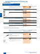
SIRIUS 3RF21 solid-state relays,
single-phase, 22.5 mm
4/66
Siemens IC 10 · 2011
4
■
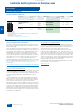
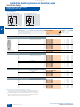
Overview
With its compact design and a width of just 22.5 mm, which stays
the same even at currents of up to 88 A, the 3RF21 solid-state
relay offers an ultra small footprint. The logical connection
method, with the power infeed from above and load connection
from below, ensures tidy installation in the control cabinet.
■
Technical specifications
1)
If two different conductor cross-sections are connected to one clamping
point, both cross-sections must lie in the range specified. If identical cross-
sections are used, this restriction does not apply.
Type 3RF21 ..-1.... 3RF21 ..-2.... 3RF21 ..-3....
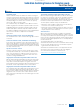
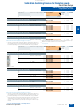
Dimensions (W x H x D) mm
22.5 x 85 x 48 22.5 x 85 x 48 22.5 x 85 x 48
General data
Ambient temperature
• During operation, derating from 40 °C °C -25 ... + 60
• During storage °C
-55 ... + 80
Installation altitude m
0 ... 1000; derating from 1000
Shock resistance acc. to IEC 60068-2-27 g/ms
15/11
Vibration resistance acc. to IEC 60068-2-6 g
2
Degree of protection
IP20
Electromagnetic compatibility (EMC)
• Emitted interference
- Conducted interference voltage
acc. to IEC 60947-4-3
Class A for industrial applications
- Emitted, high-frequency interference voltage
acc. to IEC 60947-4-3
Class B for residential, business and commercial applications
• Interference immunity
- Electrostatic discharge
acc. to IEC 61000-4-2
(corresponds to degree of severity 3)
kV Contact discharge 4; air discharge 8; behavior criterion 2
- Induced RF fields
acc. to IEC 61000-4-6
MHz 0.15 ... 80; 140 dBµV; behavior criterion 1
- Burst acc. to IEC 61000-4-4 kV
2/5.0 kHz; behavior criterion 2
- Surge acc. to IEC 61000-4-5 kV
Conductor - ground 2; conductor - conductor 1; behavior criterion 2
Connection type
Screw terminals Spring-type terminals Ring terminal
lug connections
Connection, main contacts
• Conductor cross-sections
- Solid mm
2
2 x (1.5 ... 2.5)
1)
; 2 x (2.5 ... 6)
1)
2 x (0.5 ... 2.5) --
- Finely stranded with end sleeve mm
2
2 x (1 ... 2.5)
1)
; 2 x (2.5 ... 6)
1)
;
1 x 10
2 x (0.5 ... 1.5) --
- Finely stranded without end sleeve mm
2
- 2 x (0.5 ... 2.5) --
- Solid or stranded, AWG cables
2 x (AWG 14 ... 10) 2 x (AWG 18 ... 14) --
• Terminal screw
M4 -- M5
• Tightening torque Nm
2 ... 2.5 -- 2.5 ... 2
lb.in
7 ... 10.3 -- 10.3 ... 7
• Cable lug
-DIN -- -- DIN 46234 -5-2.5, -5-6, -5-10,
-5-16, -5-25
-JIS
-- -- JIS C 2805 R 2-5, 5.5-5, 8-5,
14-5
Connection, auxiliary/control contacts
• Conductor cross-sections mm
AWG
1 x (0.5 ... 2.5), 2 x (0.5 ... 1.0)
20 ... 12
0.5 ... 2.5
20 ... 12
1 x (0.5 ... 2.5), 2 x (0.5 ... 1.0)
20 ... 12
• Stripped length mm
7 10 7
• Terminal screw
M3 -- M3
• Tightening torque Nm
0.5 ... 0.6 -- 0.5 ... 0.6
lb.in
4.5 ... 5.3 -- 4.5 ... 5.3
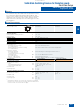
W
H
D
© Siemens AG 2010