
Data Sheet


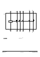

Required spacing
● with side-by-side mounting
— forwards
10mm
— upwards
10mm
— downwards
10mm
— at the side
0mm
● for grounded parts
— forwards
10mm
— upwards
10mm
— at the side
6mm
— downwards
10mm
● for live parts
— forwards
10mm
— upwards
10mm
— downwards
10mm
— at the side
6mm
Connections/ Terminals
Type of electrical connection
● for main current circuit
screw-type terminals
● for auxiliary and control current circuit
screw-type terminals
● at contactor for auxiliary contacts
Screw-type terminals
● of magnet coil
Screw-type terminals
Type of connectable conductor cross-sections
● for main contacts
— single or multi-stranded
2x (1 ... 35 mm²), 1x (1 ... 50 mm²)
— finely stranded with core end processing
2x (1 ... 25 mm²), 1x (1 ... 35 mm²)
● at AWG conductors for main contacts
2x (18 ... 2), 1x (18 ... 1)
Connectable conductor cross-section for main
contacts
● finely stranded with core end processing
1...35mm²
Connectable conductor cross-section for auxiliary
contacts
● single or multi-stranded
0.5...2.5mm²
● finely stranded with core end processing
0.5...2.5mm²
Type of connectable conductor cross-sections
● for auxiliary contacts
— single or multi-stranded
2x (0,5 ... 1,5 mm²), 2x (0,75 ... 2,5 mm²)
— finely stranded with core end processing
2x (0.5 ... 1.5 mm²), 2x (0.75 ... 2.5 mm²)
● at AWG conductors for auxiliary contacts
2x (20 ... 16), 2x (18 ... 14)
AWG number as coded connectable conductor cross
section
● for main contacts
18...1
3RT2037-1AP00 Subject to change without notice
Page 7/
10
09/11/2019 © Copyright Siemens