
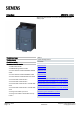
Datasheet

● at 60 °C to power-up
15W
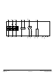
Control circuit/ Control
Type of voltage of the control supply voltage AC/DC
Control supply voltage at AC
● at 50 Hz rated value
24V
● at 60 Hz rated value
24V
Relative negative tolerance of the control supply
voltage at AC at 50 Hz
-20%
Relative positive tolerance of the control supply
voltage at AC at 50 Hz
20%
Relative negative tolerance of the control supply
voltage at AC at 60 Hz
-20%
Relative positive tolerance of the control supply
voltage at AC at 60 Hz
20%
Control supply voltage frequency 50...60Hz
Relative negative tolerance of the control supply
voltage frequency
-10%
Relative positive tolerance of the control supply
voltage frequency
10%
Control supply voltage
● at DC rated value
24V
Relative negative tolerance of the control supply
voltage at DC
-20%
Relative positive tolerance of the control supply
voltage at DC
20%
Control supply current in standby mode rated value 160mA
Holding current in the by-pass mode operating rated
value
360mA
Starting current at close of by-pass contact maximum 0.75A
Inrush current peak at connect of control supply
voltage maximum
3.3A
Duration of inrush current peak at connect of control
supply voltage
12.1ms
Design of the overvoltage protection Varistor
Design of short-circuit protection for control circuit 4 A gG fuse (Icu=1 kA), 6 A quick-acting fuse (Icu=1 kA), C1
miniature circuit breaker (Icu= 600 A), C6 miniature circuit breaker
(Icu= 300 A); Is not part of scope of supply
Inputs/ Outputs
Number of digital inputs 1
Number of inputs for thermistor connection 0
Number of digital outputs 3
● not parameterizable
2
Digital output version 2 normally-open contacts (NO) / 1 changeover contact (CO)
Number of analog outputs 1
3RW5213-1AC04 Subject to change without notice
Page 4/
10
06/04/2019 © Copyright Siemens