
User Manual


Safety notes
2.3 ATEX for intrinsically safe circuits
SIRIUS ACT 3SU1 pushbuttons and signaling devices
System Manual, 02/2015, A5E03457306020A/RS-AB/002
27
Setting up an intrinsically safe area
To avoid closing and opening sparks, the capacitance and inductance of an intrinsically safe
circuit are also limited depending on the maximum voltage and current values. No sparks
and no thermal effects that could result in the ignition of a potentially explosive atmosphere
can occur either in standard operation or in the event of a fault. For this reason, intrinsically
safe circuits may be connected or disconnected under power during operation because
safety is ensured even in the event of short-circuit or interruption.
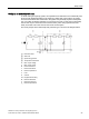
The circuit principle of the intrinsically safe protection type is shown in the diagram below:
①
Hazardous area
②
Safe area
③
Spark energy limited
④
Temperature rise limited
U
0
Max. output voltage
I
0
Max. output current
R
i
Internal resistance
L
i
Internal inductance
C
i
Internal capacitance
F
Fuse
D
Z diode
PA
Equipotential bonding
R
a
External resistance
L
a
External inductance
C
a
External capacitance