
User Manual

IO-Link
10.2 Design of a command point with ID key-operated switch
SIRIUS ACT 3SU1 pushbuttons and signaling devices
214 System Manual, 02/2015, A5E03457306020A/RS-AB/002
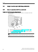
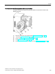
10.2.2
Operating principle of the command point with ID key-operated switch
The ID key-operated switch is used primarily to set the current key position by rotation. To
set the current key position, the rotary knob of the ID key-operated switch is turned clockwise
or counter-clockwise. There is an opening in the rotary knob into which the ID key is
inserted. Actuation is only possible if a valid ID key has been detected, and the authorization
level of the relevant ID key corresponds to, or is higher than, the current key position. The
rotary knob can be turned clockwise and counter-clockwise through 360° in 45-degree steps.
The switch position delay is started and the temporary key position is incremented by turning
clockwise.
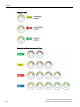
The temporary key position is indicated by the illuminated surfaces in the ID key-operated
switch flashing green. During the switch position delay, the temporary key position can be
changed by turning the knob clockwise or counter-clockwise. The switch position delay is
restarted by turning the knob clockwise. During the switch position delay, the outputs are not
yet affected by the temporary key position. After the delay has expired, the temporary key
position is adopted as the current key position, and the outputs are switched in accordance
with this position.
By turning counter-clockwise, the current key position is changed to 0, and the outputs are
switched immediately in accordance with this position.
Note
In a configuration with electronic module for ID
key-operated switches for IO-Link, the
parameters can be set via IO
-Link.
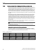
Settings on the electronic module for ID key-operated switches
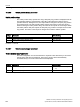
The electronic modules for ID key-operated switches have five digital outputs. Setting of
outputs 0 to 3 depends on the current key position and the module settings. If a valid ID key
has been detected, output 4 is active; otherwise output 4 is inactive.
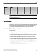
Table 10- 1 Adjustment method
Key position
Output
0
1
2
3
0
Inactive
Inactive
Inactive
Inactive
1
Active
Inactive
Inactive
Inactive
2
Inactive
Active
Inactive
Inactive
3
Inactive
Inactive
Active
Inactive
4
Inactive
Inactive
Inactive
Active