
User Manual


3SU14 modules
7.2 Mounting
SIRIUS ACT 3SU1 pushbuttons and signaling devices
System Manual, 02/2015, A5E03457306020A/RS-AB/002
143
7.2
Mounting
7.2.1
Front plate mounting of the modules
Procedure
1. Insert the actuating or signaling element from the front through the mounting opening of
the front plate.
2. Fit the holder from behind (wiring side) onto the actuating or signaling element and lock it
into place.
3. The unit must be aligned before finally tightening and securing against twisting.
4. Turn the screw at the holder until the actuating or signaling element is fixed securely and
cannot vibrate or twist (tightening torque 1.0 to 1.2 Nm).
5. Snap the contact module(s) from behind onto the holder.
To do this, hold the modules so that they are tilted downward slightly and place them onto
the holder from behind and then press them upwards until you feel the module latch in
the holder.
Single- or two-pole contact modules can be mounted on the holder.
6. Ensure secure latching.
7. Connect the cables to the modules. You can find the relevant information in Chapter
"Wiring (Page 144)".
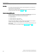
7.2.2
Mounting on printed-circuit boards
Procedure
1. Insert the actuating or signaling element (A) from the front through the mounting opening
of the front plate (B).
2. Fit the holder (C) from behind onto the actuating or signaling element and lock it into
place.
3. Turn the screw at the holder until the actuating or signaling element is fixed securely and
cannot vibrate or twist.
4. Equip the printed-circuit board (F) with the components.
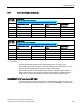
Note
Number of PCB carriers
One or more PCB carriers must be used, depending on the appl
ication.
If the printed
-circuit board is attached, one PCB carrier is sufficient. For an unattached
printed
-circuit board, at least two PCB carriers must be used.